Dual Controller Configuration
A dual control module configuration eliminates a single point of failure in the array. If the active control module
fails, the secondary control module takes over immediately with no interruption of service. This gives you time to
replace the failed control module while your volumes and data remain accessible.
Interpreting Control Module LEDs
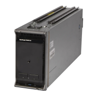
Control module status LEDs are shown in Figure 24. Control module status LEDs are described in Table 5.
Figure 24: Control Module Status LEDs
Table 5: Control Module LED Descriptions
Callout LED Name State Description
1 Power
Off
On (steady green)
No power.
Power/OK.
2
Activity Off
Steady green
Steady amber
No power, secondary control module is not synchronized
with active control module, or error.
Active control module (serving network I/O).
Secondary control module. Cache is synchronized with
active control module.
Identifying Control Module Failures
You can identify a failure in a control module by:
• LEDs on the control module itself. See Interpreting Control Module LEDs on page 37
37
Dell EqualLogic PS-M4110 Hardware Owner's Manual Interpreting Control Module LEDs