1. Press the enclosure power switch to turn off the system.
CAUTION: To avoid damaging the modules, you must remove all the modules installed in the enclosure before
removing the front module cage assembly and midplane.
NOTE: If you remove the chassis from the rack, you must remove all modules before moving the chassis. Do
not use the LCD display as a handle when moving the chassis.
2. Remove the following:
a) All the blades
b) Power supply modules
c) Fan modules
d) CMC module(s)
e) iKVM module
f) I/O modules
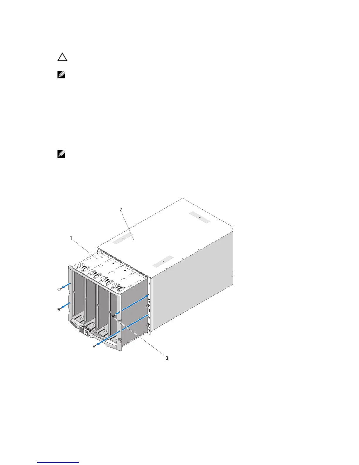
3. Remove the four Torx T20 screws securing the front module cage assembly to the enclosure.
NOTE: The empty cage assembly weighs 21 kg (47 lb). Obtain assistance when removing the cage assembly
from the enclosure.
4. Slide the cage out from the enclosure.
5. Disconnect the control-panel cable from the midplane by pressing the small latch at each end of the connector.
6. Remove the four Torx T15 screws securing the midplane to the back of the front cage assembly, and remove the
midplane.
Figure 49. Removing and Installing the Front Module Cage Assembly
1. front module cage assembly
2. enclosure
3. Torx T20 screws (4)
88
 Loading...