EasyManuals Logo

Dell External M1000e t User Manual

Dell External M1000e t
103 pages
To Next Page IconTo Next Page
To Previous Page IconTo Previous Page
Page #14 background imageLoading...
Page #14 background image
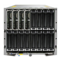
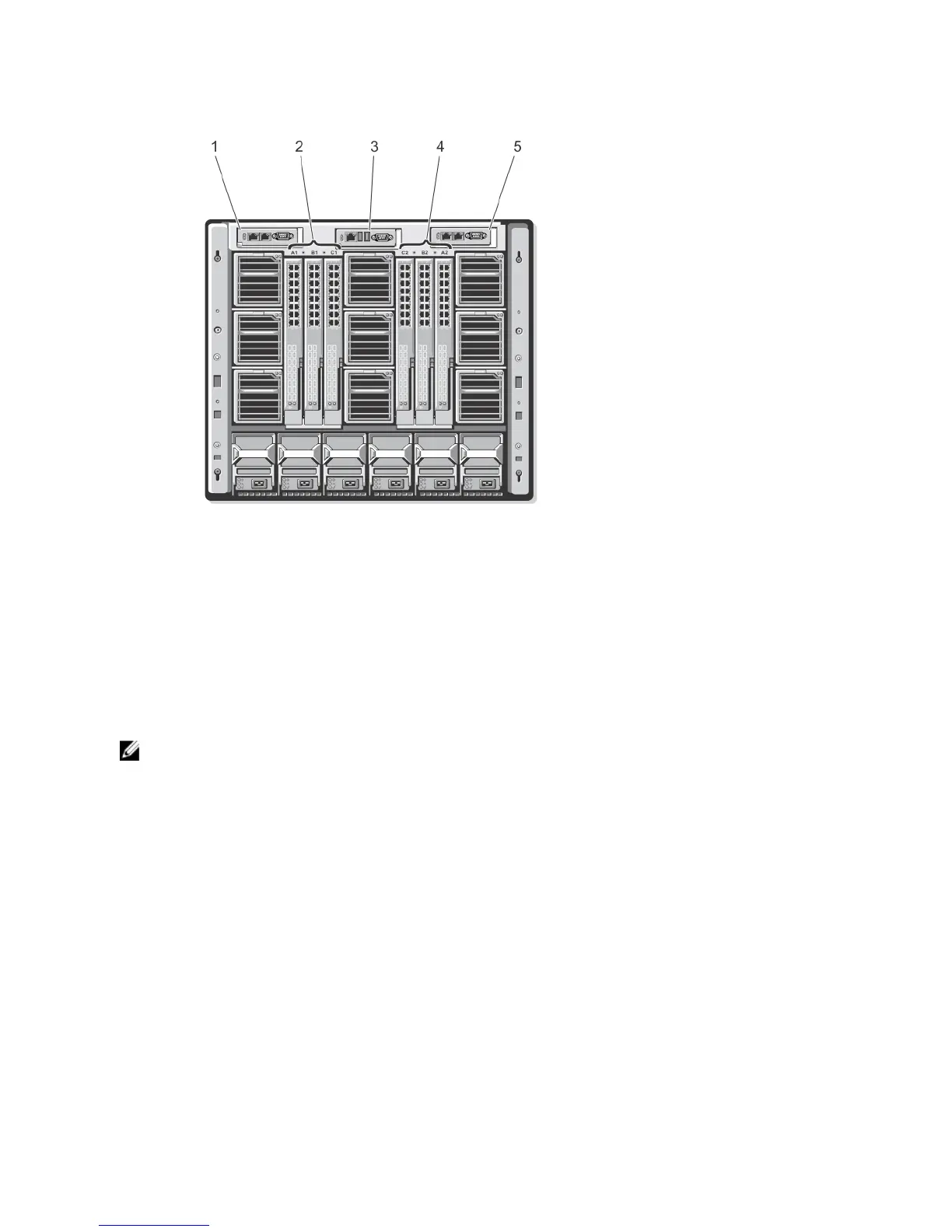
Figure 8. Back-Panel Module Bay Numbering
1. CMC 1 (primary CMC module)
2. A1 B1 C1 (left I/O modules)
3. iKVM (iKVM module)
4. C2 B2 A2 (right I/O modules)
5. CMC 2 (secondary CMC module)
Power Supply Indicators
NOTE: The AC power supplies must be connected to a Power Distribution Unit (PDU), not directly to an electrical
outlet. For DC power supplies, plug the other end of the power cables to a branch-protected DC power source.
The power supplies require a 100 V to 240 V power source.
A 2700 W power supply provides 1350 W input power, if connected to a 110 V AC power source (optional).
14

Table of Contents

Questions and Answers:

Question and Answer IconNeed help?

Do you have a question about the Dell External M1000e t and is the answer not in the manual?

Dell External M1000e t Specifications

General IconGeneral
Rack Units10U
ModelM1000e
Power SupplyUp to 6 power supply units (PSUs)
Form FactorEnclosure
CoolingRedundant, hot-swappable fans
ManagementDell Chassis Management Controller (CMC)
CompatibilityDell PowerEdge blade servers
NetworkingFibre Channel, InfiniBand

Related product manuals