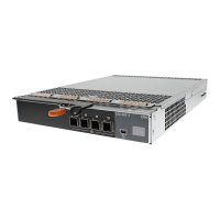
Avocent iKVM Analog Switch Module (Optional)
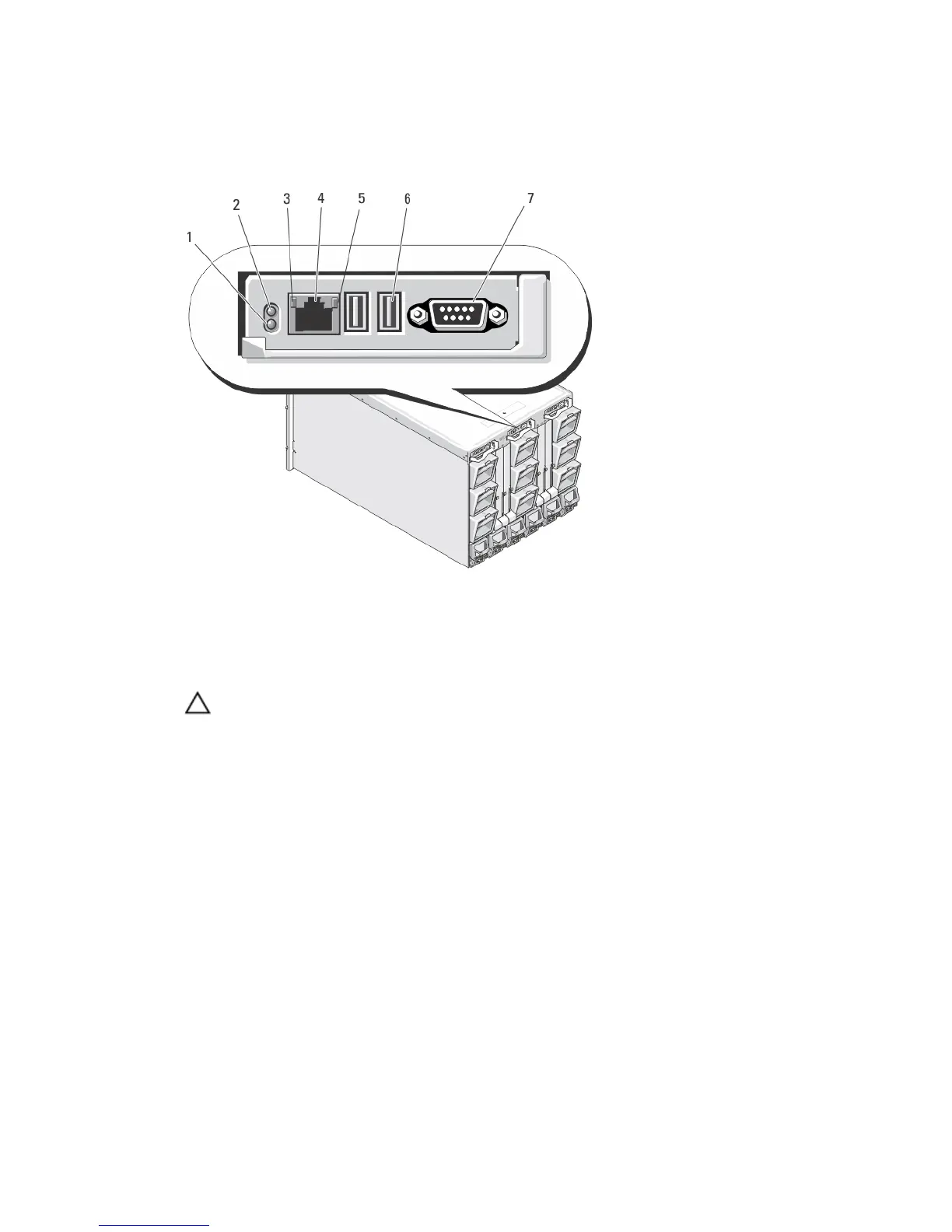
Figure 11. Avocent iKVM Switch Module
1. status/identification indicator
2. power indicator
3. link indicator
CAUTION: Do not connect the ACI port to a
LAN device such as a network hub. Doing so
may result in equipment damage.
4. Analog Console Interface (ACI) port (for tiering
connection only)
5. activity indicator
6. USB connectors (2) for keyboard and mouse
7. video connector
Avocent Analog iKVM Switch Module Indicators
Module Indicator Description
Power indicator
Off iKVM switch does not have power.
Green iKVM switch has power.
Green flashing Firmware upgrade in progress.
Status/Identification
indicator
Blue blinking iKVM module is being identified.
Amber flashing System fault or error condition.
USB connectors Allows a keyboard and mouse to be connected to the system.
17