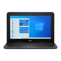
What does PCI, video card chip failure mean on a Dell Latitude 3410 Laptop?
- MMartin PageSep 8, 2025
If the diagnostic light code 3,2 appears on your Dell Laptop, it indicates a PCI, video card/chip failure.

What does PCI, video card chip failure mean on a Dell Latitude 3410 Laptop?
If the diagnostic light code 3,2 appears on your Dell Laptop, it indicates a PCI, video card/chip failure.
What does LCD power rail failure mean on a Dell Latitude 3410?
If your Dell Laptop is showing a diagnostic light code of 2,8, it indicates an LCD power rail failure. It is suggested to replace the system board and LCD.
What does coin-cell battery failure mean on a Dell Latitude 3410?
If your Dell Laptop displays a diagnostic light code of 3,1, it means there is a coin-cell battery failure.
What does recovery image not found mean on a Dell Laptop?
If your Dell Laptop displays a diagnostic light code of 3,3, it means the recovery image was not found.
What does recovery image found but invalid mean on a Dell Latitude 3410?
If your Dell Laptop is showing a diagnostic light code of 3,4, it indicates that the recovery image was found but is invalid.
| Graphics | Intel UHD Graphics |
|---|---|
| Display | 14-inch HD (1366x768) or FHD (1920x1080) |
| Storage | Up to 1TB SSD |
| Operating System | Windows 10 Pro |
| Battery | 3-Cell, 42 WHr, Integrated |
| Ports | 2 x USB 3.1, 1 x USB 2.0, 1 x HDMI, 1 x RJ-45, 1 x SD card reader |
| Wireless | Wi-Fi 6 (802.11ax), Bluetooth 5.0 |
Identifies the base cover component of the system.
Identifies the battery component of the system.
Identifies the DC-in port component of the system.
Identifies the heatsink component of the system.
Identifies the memory modules component of the system.
Identifies the speakers component of the system.
Identifies the system board component of the system.
Identifies the touchpad component of the system.
Identifies the palmrest assembly component of the system.
Identifies the display assembly component of the system.
Identifies the power button module component of the system.
Identifies the coin-cell battery component of the system.
Identifies the I/O board component of the system.
Identifies the fan assembly component of the system.
Identifies the WLAN card component of the system.
Identifies the solid-state drive component of the system.
Identifies the hard drive assembly component of the system.
Provides essential safety guidelines before working on the computer.
Outlines initial steps and precautions before disassembling the computer.
Details primary safety steps and precautions for disassembly/reassembly.
Explains standby power behavior and discharge procedures.
Describes the method of connecting grounding conductors for ESD protection.
Explains the risks and prevention of ESD damage to components.
Details the components and usage of an ESD field service kit.
Lists and describes the items included in an ESD field service kit.
Summarizes the recommendations for ESD protection during service.
Provides steps to follow after completing internal computer service.
Lists the essential tools required for disassembly and reassembly.
Details the types and quantities of screws used in the computer.
Section dedicated to the microSD card.
Provides steps for removing the microSD card.
Provides steps for installing the microSD card.
Section dedicated to the base cover.
Details the procedure for removing the computer's base cover.
Details the procedure for installing the computer's base cover.
Section dedicated to the system's battery.
Lists critical safety precautions for handling lithium-ion batteries.
Provides steps to disconnect the battery cable from the system board.
Provides steps to reconnect the battery cable to the system board.
Details the procedure for removing the computer's battery.
Details the procedure for installing the computer's battery.
Section dedicated to memory modules.
Details the procedure for removing a memory module.
Details the procedure for installing memory modules.
Section dedicated to the Wireless Local Area Network card.
Details the procedure for removing the WLAN card.
Details the procedure for installing the WLAN card.
Section dedicated to the coin-cell battery.
Details the procedure for removing the coin-cell battery.
Details the procedure for installing the coin-cell battery.
Section dedicated to the DC-in port.
Details the procedure for removing the DC-in port.
Details the procedure for installing the DC-in port.
Section dedicated to the solid-state drive.
Details the bracket for the solid-state drive.
Details the procedure for removing an M.2 2280 solid-state drive.
Details the procedure for installing an M.2 2280 solid-state drive.
Details the procedure for removing an M.2 2230 solid-state drive.
Details the procedure for installing an M.2 2230 solid-state drive.
Details the procedure for installing the M.2 SSD bracket.
Section dedicated to the hard drive.
Details the procedure for removing the computer's hard drive.
Details the procedure for installing the computer's hard drive.
Section dedicated to the touchpad.
Details the procedure for removing the touchpad.
Details the procedure for installing the touchpad.
Section dedicated to the computer's speakers.
Details the procedure for removing the speakers.
Details the procedure for installing the speakers.
Section dedicated to the fan assembly.
Details the procedure for removing the fan assembly.
Details the procedure for installing the fan assembly.
Section dedicated to the heatsink assembly.
Details removing the heatsink for discrete graphics.
Details installing the heatsink for discrete graphics.
Details removing the heatsink for UMA (Integrated Graphics).
Details installing the heatsink for UMA graphics.
Section dedicated to the system board.
Details removing the system board for discrete graphics.
Details installing the system board for discrete graphics.
Details removing the system board for UMA graphics.
Details installing the system board for UMA graphics.
Section dedicated to the I/O Board.
Details the procedure for removing the I/O board.
Details the procedure for installing the I/O board.
Section dedicated to the power button.
Details the procedure for removing the power button.
Details the procedure for installing the power button.
Section dedicated to the display assembly.
Details the procedure for removing the display assembly.
Details the procedure for installing the display assembly.
Section dedicated to the display bezel.
Details the procedure for removing the display bezel.
Details the procedure for installing the display bezel.
Section dedicated to the display panel.
Details the procedure for removing the display panel.
Details the procedure for installing the display panel.
Section dedicated to the camera module.
Details the procedure for removing the camera module.
Details the procedure for installing the camera module.
Section dedicated to the Display (eDP) cable.
Details the procedure for removing the display cable.
Details the procedure for installing the display cable.
Section dedicated to the display back cover assembly.
Details the procedure for replacing the display back cover.
Section dedicated to the palmrest assembly.
Details the procedure for removing the palmrest assembly.
Provides information on the system's built-in hardware diagnostic tool.
Step-by-step guide on how to run SupportAssist diagnostics.
Explains the meaning of various system status and diagnostic lights.
Provides steps to resolve Wi-Fi connectivity issues by power cycling network devices.
Guide on how to download necessary drivers for Windows operating systems.
Explains how to access and use the system's boot menu.
Describes the keyboard keys used for navigating system setup.
Provides general hardware specifications and no modifiable settings.
Details battery and AC adapter related information in BIOS.
Details processor related information in BIOS.
Details memory related information in BIOS.
Details device related information in BIOS.
Covers settings related to system boot sequence and configuration.
Details settings for integrated hardware devices like camera, audio, and USB.
Covers storage-related settings such as SATA operation and SMART reporting.
Covers display settings such as brightness and EcoPower.
Covers network and wireless device connection settings.
Covers various power management settings for the system.
Covers security-related settings including TPM and password bypass.
Continues security settings like SHA-256, TPM state, and SMM security.
Covers system and setup password configuration.
Covers settings related to BIOS and OS recovery options.
Covers system management settings like Service Tag and boot behavior.
Covers keyboard settings including Numlock and backlight.
Covers settings related to boot process behavior and warnings.
Covers settings related to hardware virtualization technologies.
Covers performance-related settings like CPU cores and speed.
Covers BIOS, Thermal, and Power event logs.
Provides instructions for updating BIOS from within the Windows operating system.
Details precautions for BIOS updates when BitLocker is active.
Provides instructions for updating BIOS using a USB flash drive.
Explains how to set system and setup passwords for security.
Step-by-step guide to assign a system setup password.
Step-by-step guide to delete or change existing system/setup passwords.
Provides information on how to contact Dell support for assistance.


