Installing System Components 111
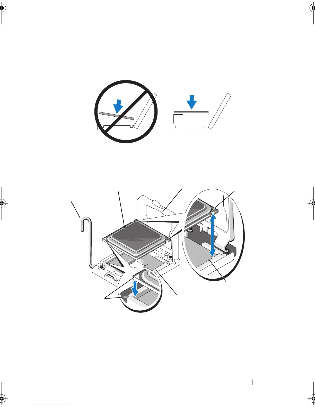
Figure 3-14. Keeping the Processor Parallel to the Socket
Figure 3-15. Aligning the Processor With the Socket Keys
1 socket-release lever 2 processor
3 processor shield 4 notch in processor (2)
5 socket key (2) 6 ZIF socket
7 pin 1 indicators (2)
6
1
2
4
3
5
7
book.book Page 111 Monday, June 15, 2009 11:33 AM