112 Installing System Components
8
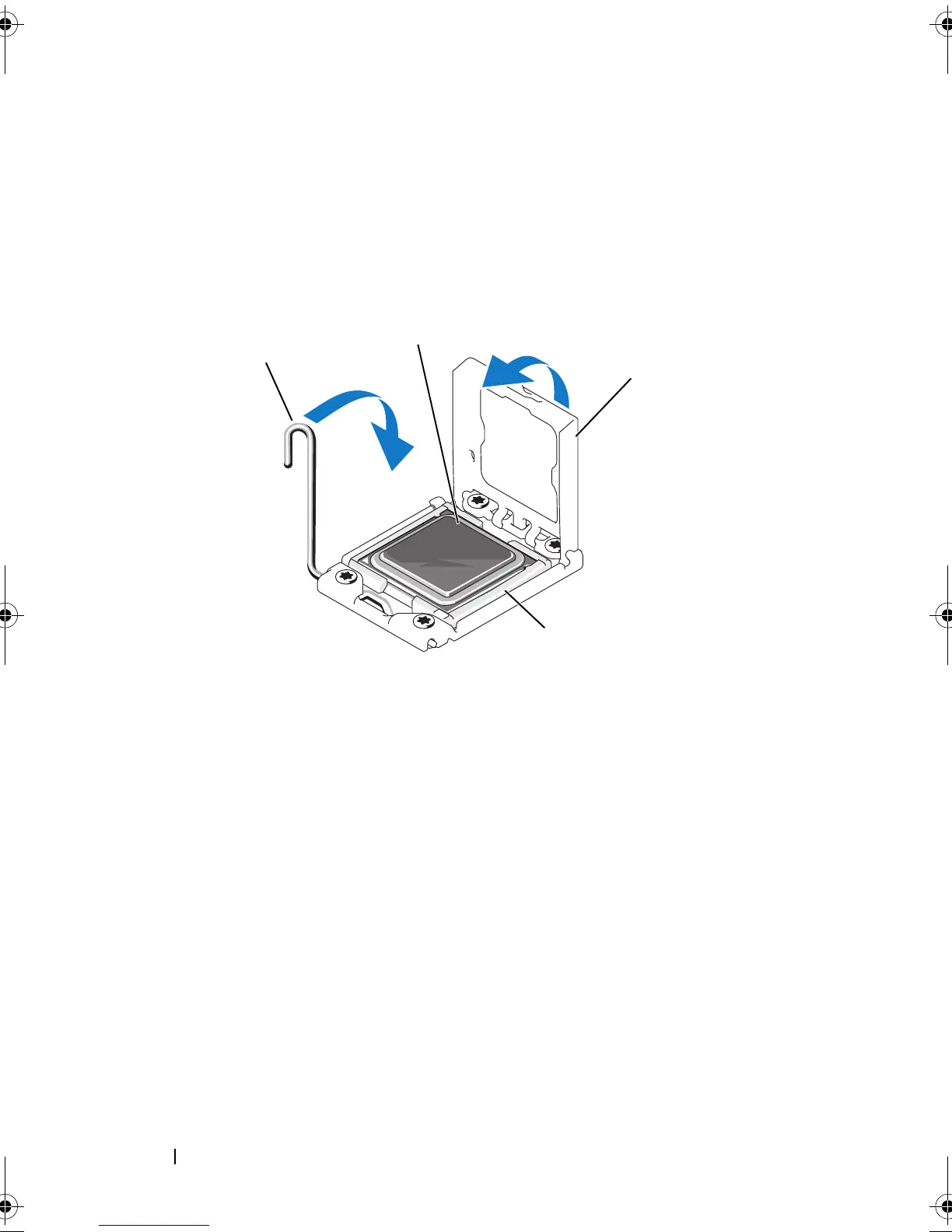
Verify that the processor is properly aligned and seated.
9
Close the processor shield. See Figure 3-16.
10
R
otate the socket-release lever down until it snaps into place. See
Figure 3-16.
Figure 3-16. Installing a Processor
1 socket-release lever 2 processor
3 processor shield ZIF socket
1
3
4
book.book Page 112 Monday, June 15, 2009 11:33 AM