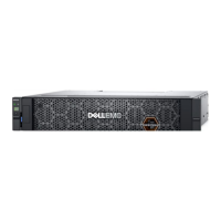
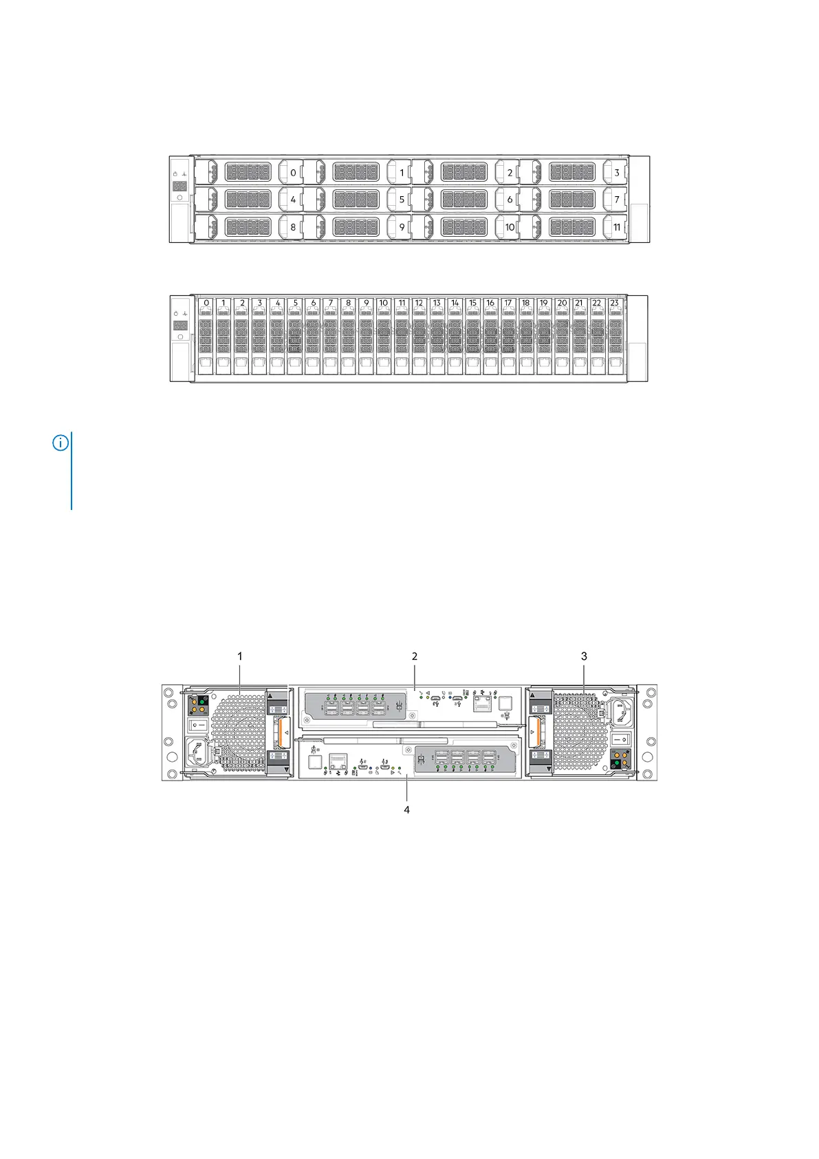
2U enclosure front panel
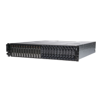
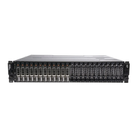
In the following figures, integers on disks indicate drive slot numbering sequence.
Figure 7. 2U12 enclosure system—front panel components
Figure 8. 2U24 enclosure system—front panel components
NOTE:
● For information about enclosure front panel LEDs, see 2U enclosure Ops panel.
● For information about disk LEDs for LFF and SFF disk modules, see Using LEDs on page 70.
● For information about the optional 2U enclosure front bezel, see Attach or remove the front bezel of a 2U enclosure.
2U enclosure rear panel
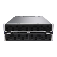
The controller modules and IOMs use alphabetic designators, and the Power Cooling Modules (PCMs) use numeric designators
to identify the slots in a 2U enclosure.
There are two redundant controller modules that use a series of LEDs to reflect host connectivity status. You can monitor the
LEDs from the rear panel area to determine system status.
Figure 9. 2U controller enclosure—rear panel components
1.
PCM 0 2. Controller module A
3. PCM 1 4. Controller module B
12 Storage system hardware
 Loading...