EasyManuals Logo

Dell PS Series User Manual

Dell PS Series
51 pages
To Next Page IconTo Next Page
To Previous Page IconTo Previous Page
Page #24 background imageLoading...
Page #24 background image
Installation and Setup Installing a PS4000 Array
2–14
Serial Cable Pinout Information
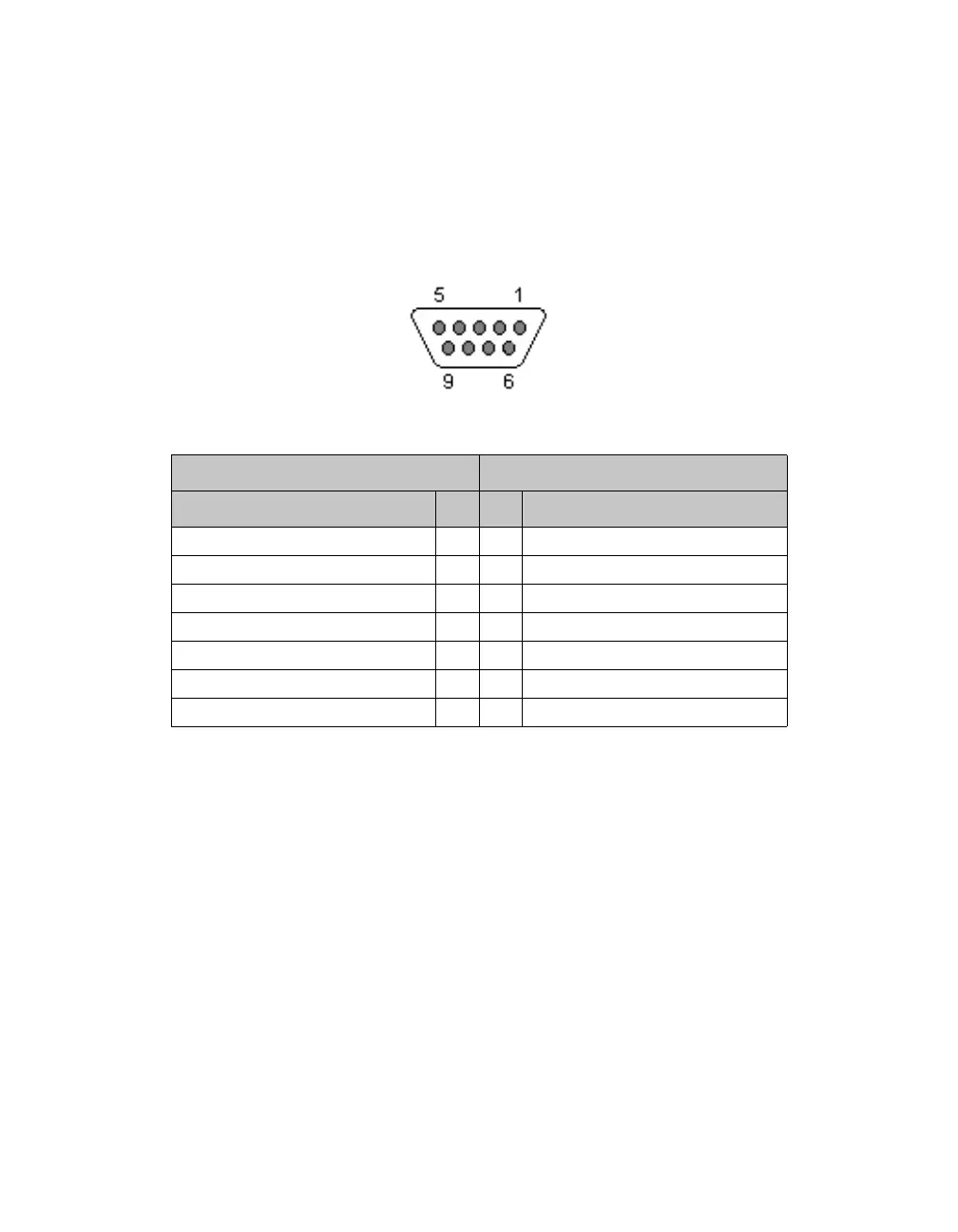
Figure 2-9 shows the pin locations on the DB9 connectors on the serial cable
shipped with the array, and Table 2-5 lists the pinout information for the cable.
Figure 2-9: Serial Cable DB9 Connector - Pin Locations
Table 2-5: DB9 to DB9 Pinout Information
DB9-1 DB9-2
Function Pin Pin Function
Receive Data 2 3 Transmit Data
Transmit Data 3 2 Receive Data
Data Terminal Ready 4 6+1 Data Set Ready + Carrier Detect
System Ground 5 5 System Ground
Data Set Ready + Carrier Detect 6+1 4 Data Terminal Ready
Request to Send 7 8 Clear to Send
Clear to Send 8 7 Request to Send

Other manuals for Dell PS Series

Questions and Answers:

Question and Answer IconNeed help?

Do you have a question about the Dell PS Series and is the answer not in the manual?

Dell PS Series Specifications

General IconGeneral
CategoryStorage
TypeSAN (Storage Area Network)
RAID SupportRAID 5, RAID 6, RAID 10
ConnectivityiSCSI
ManagementDell Storage Manager
Data ProtectionSnapshots, replication
Operating System CompatibilityWindows, Linux, VMware, Hyper-V
CapacityVaries by model (e.g., 4TB to 1PB)
Product TypeEnterprise Storage Array

Related product manuals