11.4 PSC-232, P146 or P148
These are card sets, mounted inside the power supply.
Connect and install the PSC as follows:
• Set the DIP switch to channel 1. A2, A3, A4, A5 = OFF
and A1 = ON.
• Set the Baudrate switch to 9600 baud. A6, A7 = OFF and
A8 = ON.
• Connect the 9 pole RS232 cable between the PC comport
and the PSC.
12 Calibration of the PSC
For easy calibration, a CD with a calibration program is supplied with the PSC-488 and PSC-232. You
can download the latest version from Internet www.DeltaPowerSupplies.com
. First read the “ReadMe”
file supplied with the calibration program.
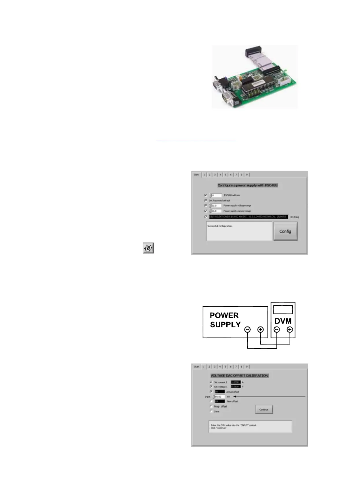
12.1 Configuration setting
•
Switch on the power of the power supply.
• Run the LabView program “PSC488_v61.exe”.
• Select “PSC488 Calibration.vi”.
• Click “OK”.
• Select tab “Start”.
• Select “PSC address” 8.
• Set the “Power supply voltage range”.
• Set the “Power supply current range”.
• When password protected, enable “Reset calibration”.
• Click “run continuously” in menu bar:
• Click “Config”.
• If configuration fails, repeat from configure.
• When configuration is successful, the program.
switches automatically to tab 1.
12.2 Voltage DAC Offset calibration
•
Connect a digital mV meter to the output terminals of
the power supply.
• Click “Continue”.
The program sets the current and the voltage.
The “Actual offset” will be displayed.
• Enter the DVM value in mV.
• Click “Continue”.
• When calibration fails, repeat.
• When calibration is successful, the program switches
automatically to tab 2.
page 11 MANUAL May 2008
DELTA ELEKTRONIKA BV PSC SERIES
Screen 1: Voltage DAC Offset calibration
Voltage calibration connection
Start screen: Voltage and current configuration