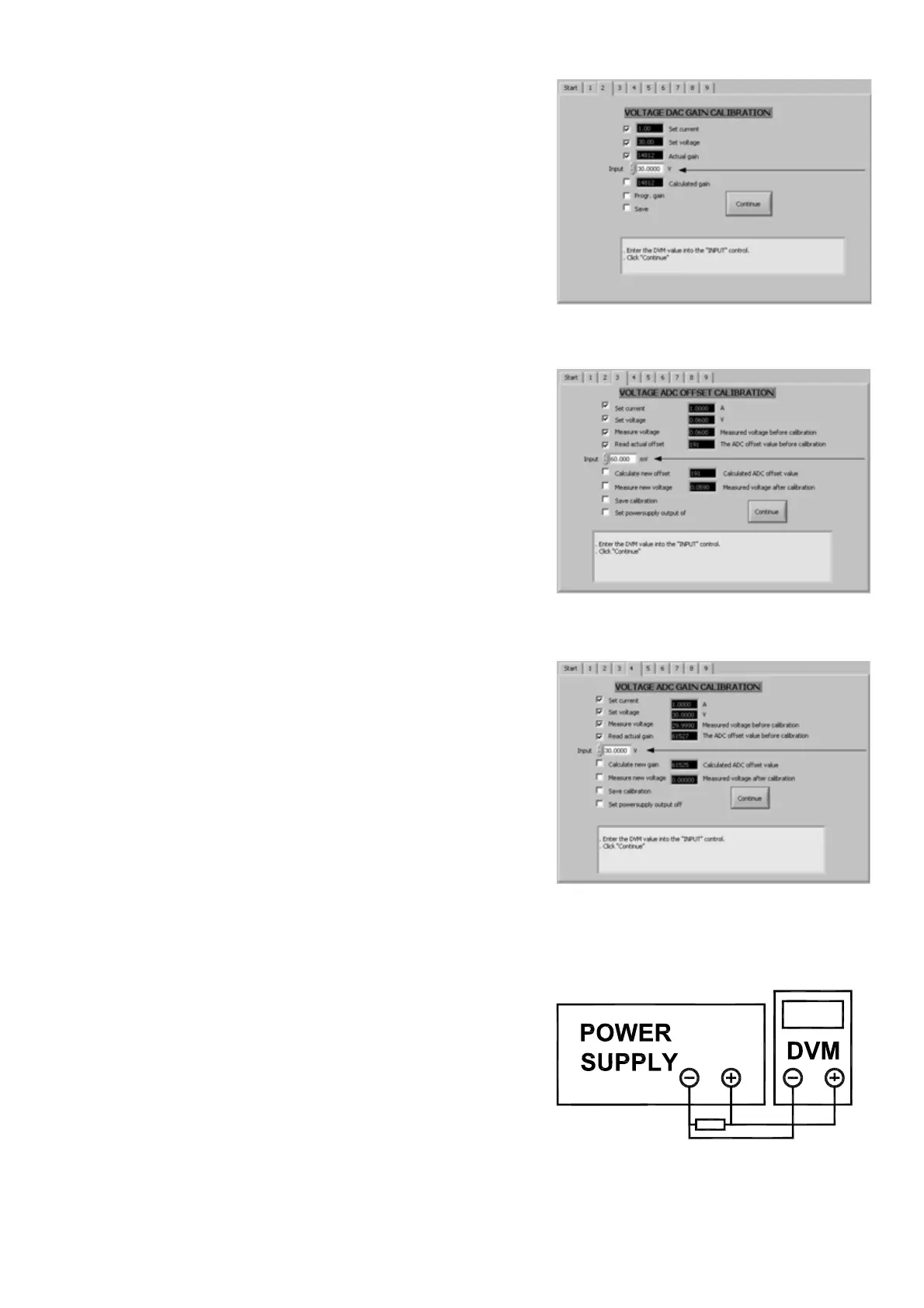
12.3 Voltage DAC gain calibration
•
Switch the digital voltage meter to the right range
(maximum output voltage of the power supply).
• Click “Continue”.
• Enter the DVM value.
• Click “Continue”.
• When calibration fails, repeat.
• When calibration is successful, the program switches
automatically to tab 3.
12.4 Voltage ADC Offset calibration
•
Switch the digital voltage meter to the right range.
See “Set voltage”.
• Click “Continue”.
• Enter the DVM value.
• Click “Continue”.
• When calibration fails, repeat.
• When calibration is successful, the program switches
automatically to tab 4.
12.5 Voltage ADC gain calibration
•
Switch the digital voltage meter to the right range
(maximum output voltage of the power supply).
• Click “Continue”.
• Enter the DVM value into “Input” control.
• Click “Continue”.
• Check “Measure new voltage”.
• Click “Continue”.
• When calibration fails, repeat.
• When calibration is successful, the program switches
automatically to tab 5.
12.6 Current DAC Offset calibration
The program has set the voltage and current to zero, so
you can safely change the connections of the power
supply.
• Connect a shunt and a D.V.M. (or zero flux ampere
meter) on the output terminals.
• Click “Continue”.
• The program sets the current and the voltage.
PSC SERIES DELTA ELEKTRONIKA BV
May 2008 MANUAL page 12
Screen 2: Voltage DAC gain calibration
Screen 3: Voltage ADC offset calibration
Screen 4: Voltage ADC gain calibration
Current calibration connection