9 Connections
9.1 RS232 Interface
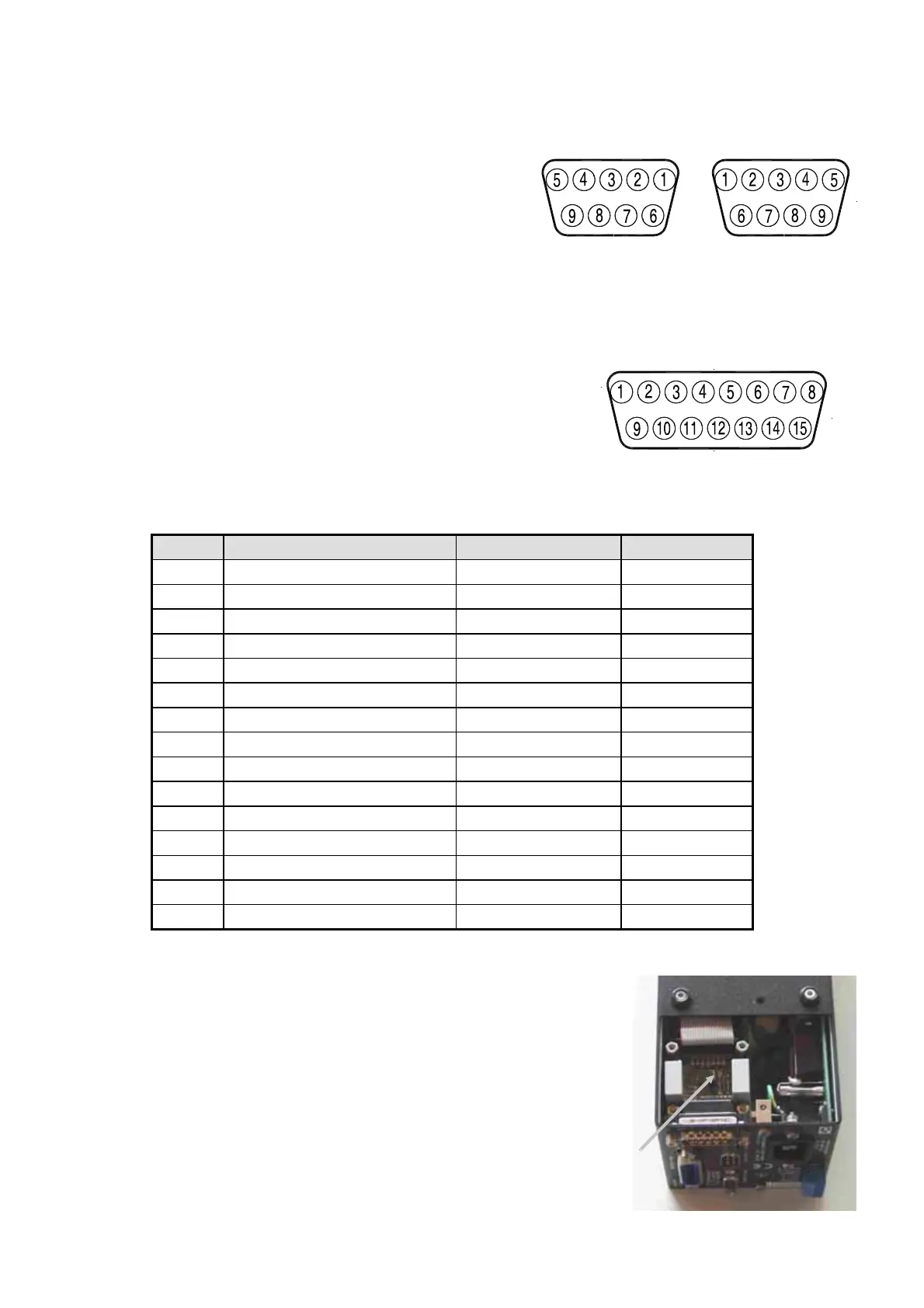
Connector from PC:
D 9 F conn.
Pin 2 TXD
Pin 3 RXD
Pin 5 GND
For connection to the PC or to the next PSC use a 1:1 cable with 1 female and 1 male connector.
Do not use a null modem cable.
Baudrate : 2400 - 9600 baud
Databits : 8
Stopbits : 2
Paritybits : none
Signal level : -10 V to +10 V
Maximum cable length : 15 m
9.2 Pin assignment of the 15P connector
PSC SERIES DELTA ELEKTRONIKA BV
May 2008 MANUAL page 8
PIN DESCRIPTION PSC In/Output Abbreviation
1 Analog common Analog common AGND
2 Current Monitor Analog Input I MON
3 Current Programming Analog Output I PROG
4 Constant Current status Digital Input CC
5 Remote Shut Down logic output Digital Output RSD
6 Power sink overload Digital Input PSO 1)2)
7 Not Connected NC
8 Digital common Digital common DGND
9 Not Connected NC
10 Voltage Monitor Analog Input V MON
11 Voltage Programming Analog Output V PROG
12 Over Temperature Digital Input O.T. 1)
13 Limit Status Digital Input LIM 1)
14 DC Fail Digital Input DCF 1)
15 AC Fail Digital Input ACF 1)
1) Check the power supply manual if the power supply supports the status.
15 pole D connector
Connector to next PSC:
D 9 M conn.
Pin 2 RXD
Pin 3 TXD
Pin 5 GND
9F Pole D connector 9M Pole D connector
2) If an SM7020-D or SM3004-D is used in combination with a
PSC module, remove the jumper on P532 or otherwise the
autoranging will not work properly.
First remove the screws from the bottom and top of the PSC in
order to remove the cover from the cabinet. Then remove the
jumper on the PCB P532.