17
ASSEMBLY
Attach the right and left support rod assemblies (E & F)as shown in Figure 13 to the upper stand assembly with two M8 x
67 carriage screws (bb), spacer (cc) and M8 locknuts (dd) as shown in Figures 13 & 14.
NOTE: Ensure the spacer (cc) is between the support rod assembly and the upper stand assembly as shown in Figure
13.
NOTE: Make sure all hardware is tight but not overtight. The amount of tightening applied to pivoting joints will affect the
stand operation.
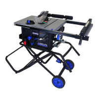
Correct stand assembly will appear as shown in Figure 14.
FIGURE 13
UPPER
STAND
ASSEMBLY
SEE
FIGURE
13
FIGURE 14
bb
+
E F
+
E F
cc
dd
 Loading...