AS Series Operation Manual
6-2
6.1
Quick Start
This chapter provides a simple example showing you how to create a traditional ladder diagram in ISPSoft.
Because you may not be familiar with IEC 61131-3 and may not understand the functions provided by ISPSoft,
the chapter does not introduce programming concepts related to IEC 61131-3. For example, the chapter does
not include POUs, function blocks, variables, and so on.
6.1.1
Example
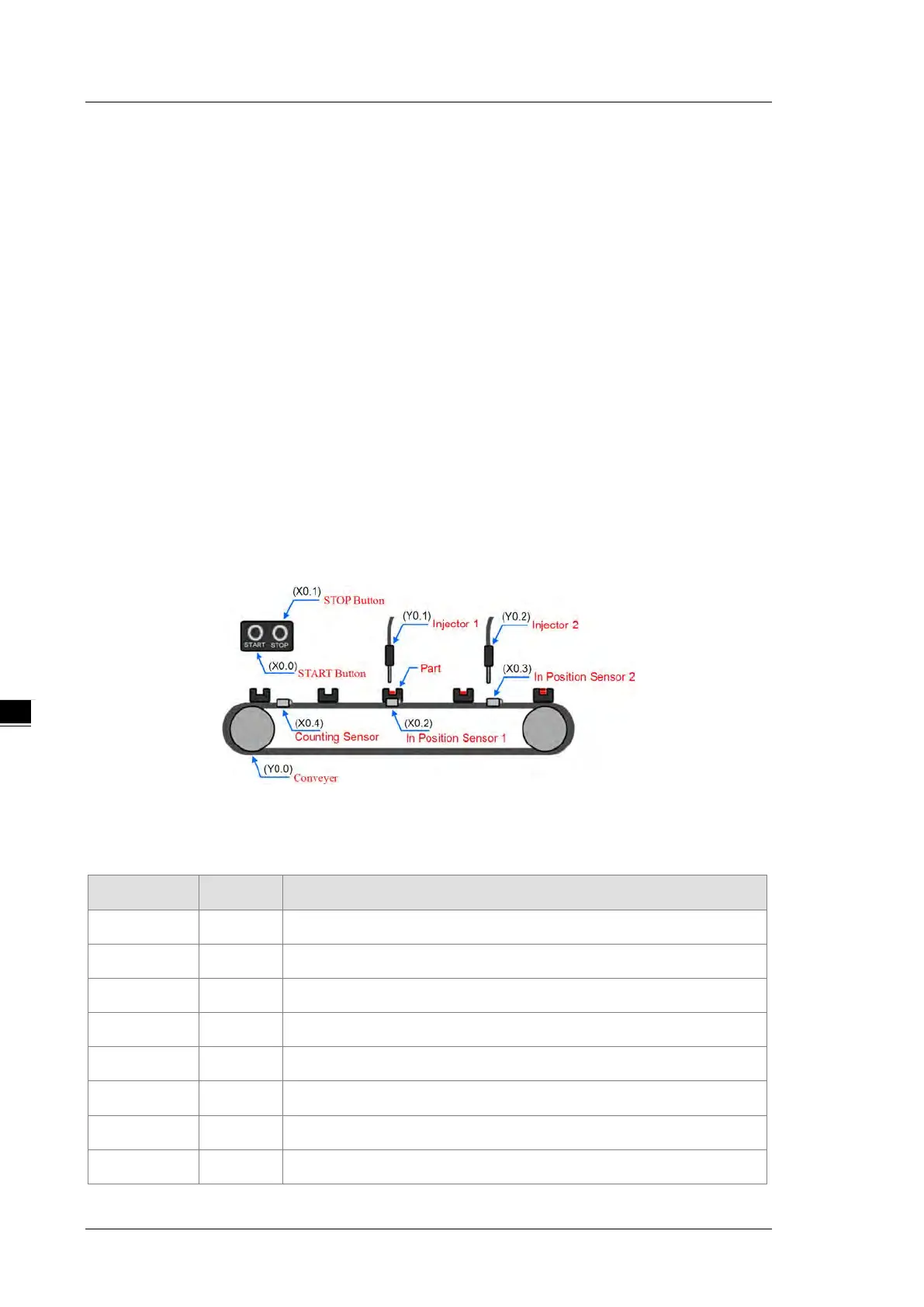
When the equipment in this example operates, the parts on the conveyor move from left to right. If a sensor
senses that a part is under an injector, the PLC sends a trigger signal to the injector, and the injector injects the
glue. The injection length is set externally and is not controlled by the PLC program . However, the PLC
program must be able to turn the trigger signal OFF so that the trigger signal can be sent next time. There are
two injectors above the conveyor, and the two injectors inject glue in the same way.
There is a sensor at the left side of the conveyor. When a part passes the sensor, the sensor value increases
by one increment. When the sensor value is 100, the internal completion flag is set to ON. The flag state can be
used by other procedures later. However, this example does not introduce the use of flag states.
6.1.2
Hardware
In this example, the AS series CPU module used is the AS332T-A.
Type ID Description
Digital input X0.0 START button
Digital input X0.1 STOP button
Digital input X0.2 In position sensor 1
Digital input X0.3 In position sensor 2
Digital input X0.4 Counting sensor
Digital output Y0.0 Conveyer
Digital output Y0.1 Trigger signal for injector 1
Digital output Y0.2 Trigger signal for injector 2
 Loading...