AS Series Operation Manual
2-57
2.7 Counter Module Specifications
2.7.1 General Specifications
2
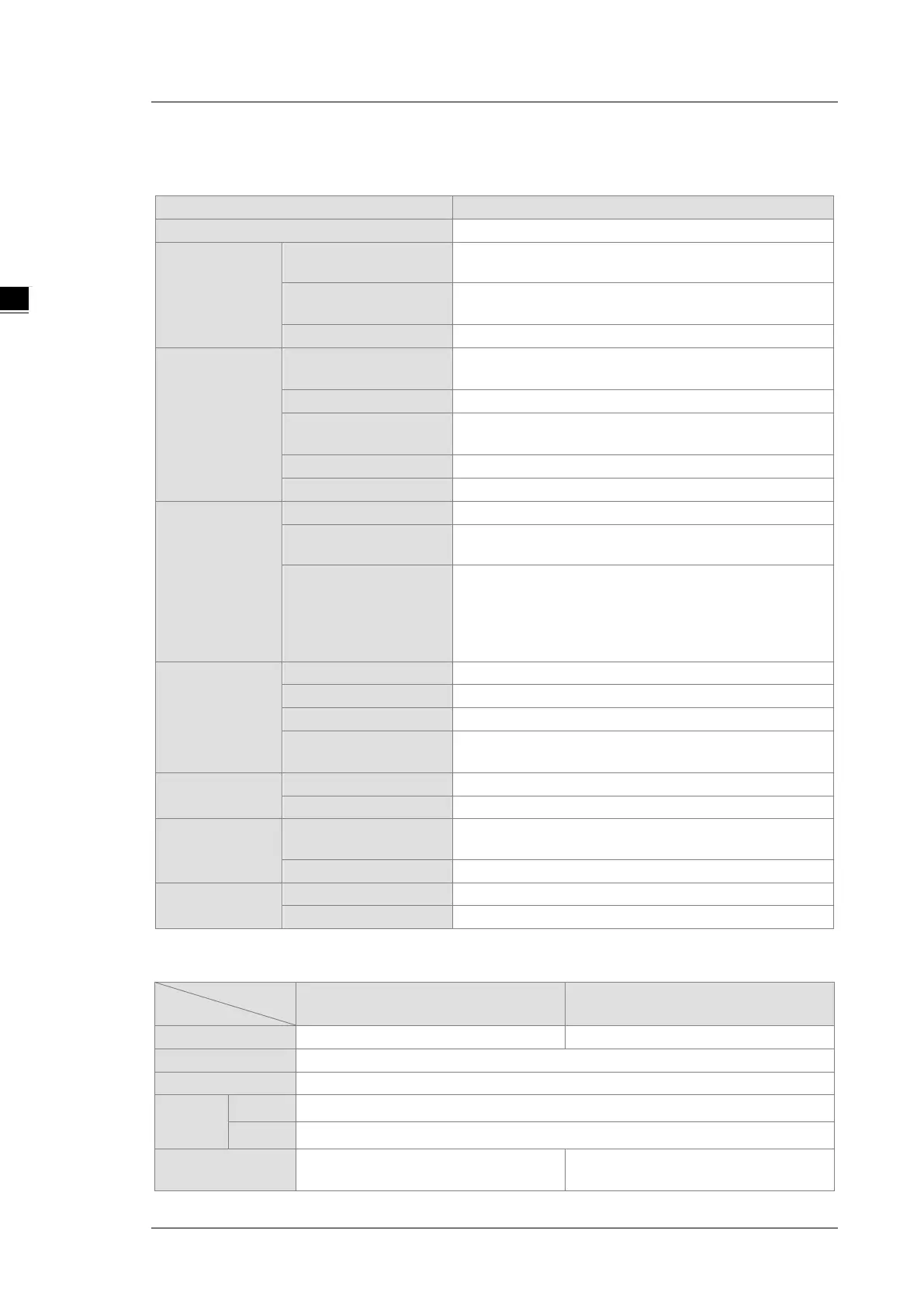
Pulse Input
Input signal type
Phase differential (A/B): x1, x2, x4; CW/CCW;
Max. transmission
200 kHz at 30 m
Circular counter, linear encoder
SSI Input
Max. data length
31-bit (The single-turn, multi-turn, and
be set.)
Max. transmission
250 kHz at 150 m, 500 kHz at 50 m, 625 kHz at 40 m,
1 MHz at 20 m, 1.25 MHz at 10 m
None, odd parity, even parity
Circular counter, absolute counter
Counter
-2147483648 ~ 2147483647 (32-bit)
Counter control
Reset, preset, gate, capture,
offset correction for absolute position
Output state check
Direction to count, counting overflow/underflow, linear
counting beyond the lower and upper limit values, SSI
feedback, SSI position exceeding the protection limit, SSI
parity checking, SSI communication status, a zero point is
set beyond SSI encoder resolution
External input
point (phase Z)
2 (one for each channel)
Reset, gate, capture
OFF, 100 μs, 200 μs to 20 ms
Min. software interrupt
10 μs (hardware response time included)
External output
point
Comparison
function
Instruction
General comparison output instruction, table comparision
output instruction
Using comparision to achieve the interrupt function
Measurement
function
Input frequency and revolution
Electrical specifications for the inputs
Model
Pulse input External input
4 (A+/B+, A-/B-) 2 (Z+/Z-)
Action
level
OFF→ON
3 V
ON→OFF
1 V
Maximum input
200 kHz
20 kHz
 Loading...