AS Series Operation Manual
12-18
12.3
Troubleshooting for I/O Modules
Introduction to troubleshotting modules
Digital I/O, analog I/O, temperature measurement, positioning, counter, load cell, and network modules can be
installed in an AS Series system. There are 2 types of error codes; error and warning. The CPU module and its
modules stop operating when errors occur. The CPU modules and its modules do not stop operating when warnings
are triggered.
12.3.1
Troubleshooting for Analog Modules (AD/DA/XA) and
Temperature Modules (RTD/TC)
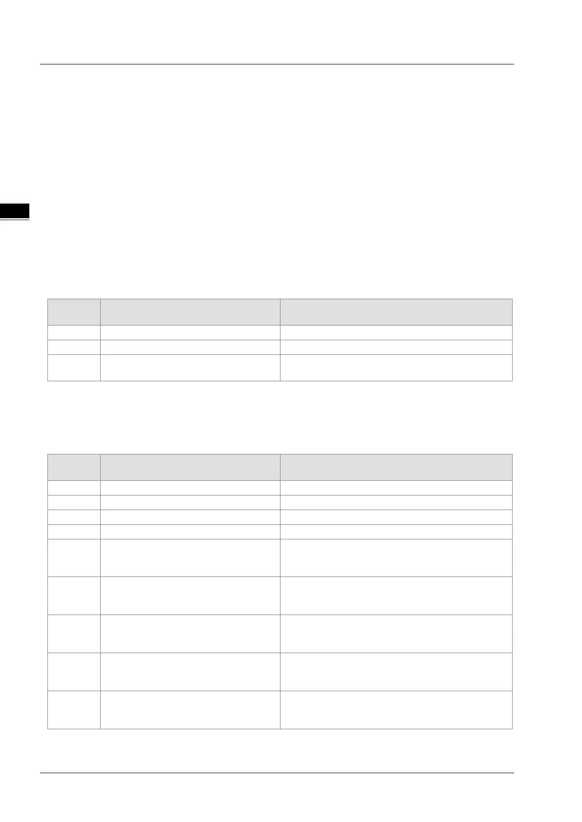
12.3.1.1 ERROR LED Indicators Are ON
You can set up HWCONFIG to have the following errors appear as warnings when they occur. Otherwise, when an error
occurs, only an error message appears.
Error
Description Solution
16#1605 Hardware failure Contact the factory.
The external voltage is abnormal.
16#1608
The factory calibration or the CJC is
Contact the factory.
12.3.1.2 ERROR LED Indicators Blinking Every 0.2 Seconds
The following errors are specified as warnings to ensure that the CPU module can still run even when the warnings are
triggered by its AIO modules. The following first 4 error codes are set as warnings by default in HWCONFIG; CPU must
STOP running immediately when the first 4 errors occur.
Error
Description Solution
16#1801 The external voltage is abnormal. Check the power supply.
The factory calibration is abnormal.
16#1808
The signal received by channel 1
exceeds the range of analog inputs
Check the signal received by channel 1
16#1809
The signal received by channel 2
exceeds the range of analog inputs
Check the signal received by channel 2
16#180A
The signal received by channel 3
exceeds the range of analog inputs
Check the signal received by channel 3
16#180B
The signal received by channel 4
exceeds the range of analog inputs
Check the signal received by channel 4
16#180C
The signal received by channel 5
exceeds the range of analog inputs
(temperature).
Check the signal received by channel 5
 Loading...