Chapter 6 Control TerminalsC2000 Plus
6-10
Terminals Terminal Function Factory Setting (NPN mode)
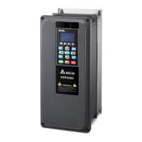
ACI
Analog current input
Figure 6-18
Impedance: 250 Ω
Range: 0–20mA / 4–20mA / 0–10V = 0–Max.
Operation Frequency (Pr.01-00)
ACI Switch, factory setting is 4–20 mA
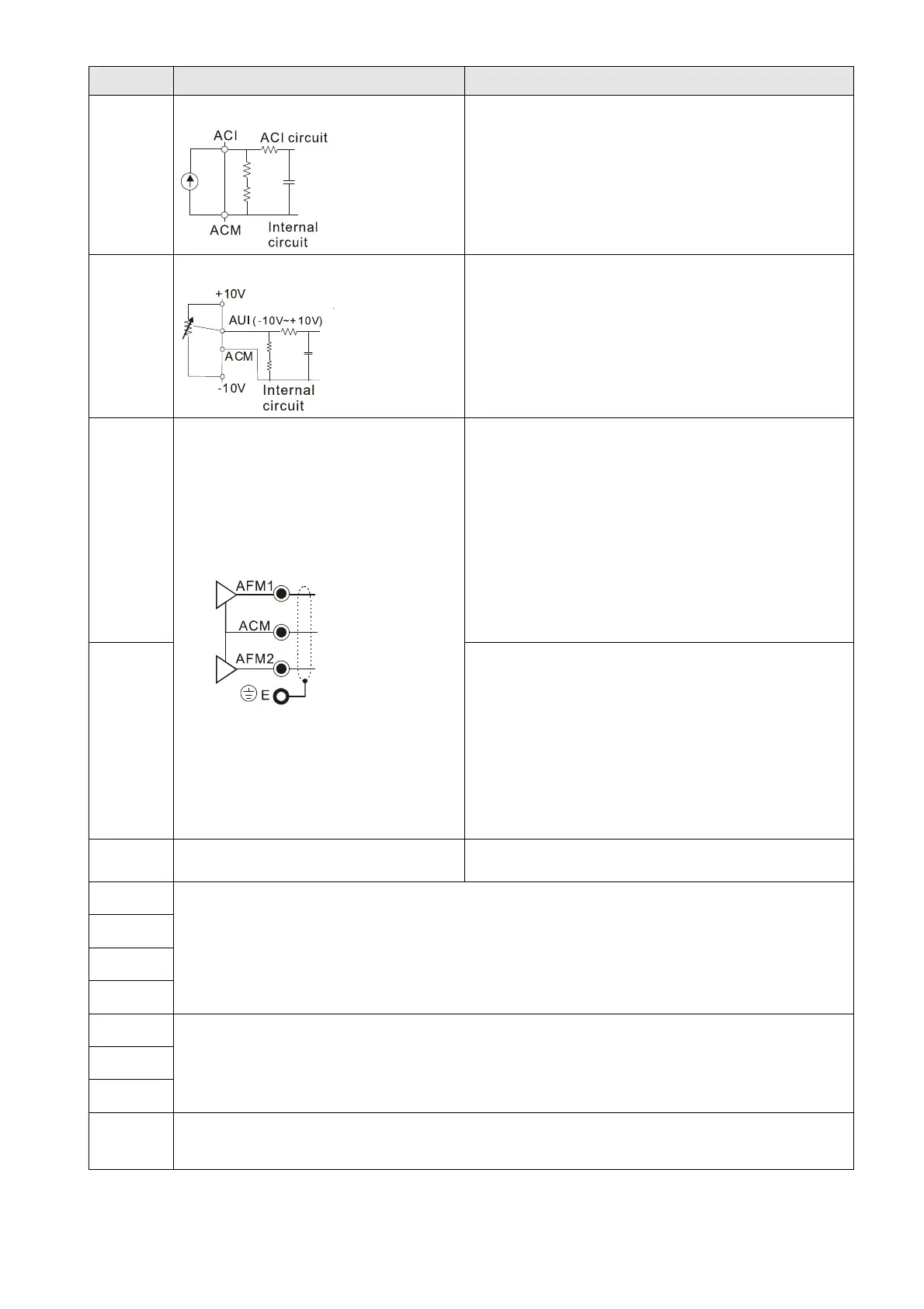
AUI
Auxiliary analog voltage input
Figure 6-19
Impedance: 20 kΩ
Range: -10– +10 V
DC
= 0–Max. Operation
Frequency (Pr. 01-00)
AFM1
Multi-function analog voltage output
Figure 6-20
0–10V Max. output current 2mA, Max. load 5 kΩ
-10–10V maximum output current 2 mA,
maximum load 5 kΩ
Output current: 2 mA max
Resolution: 0–10V corresponds to Max. operation
frequency
Range: 0–10V -10– +10V
AFM1 Switch, factory setting is 0–10V
AFM2
0–10V Max. output current 2 mA, Max. load 5 kΩ
0–20 mA Max. load 500 Ω
Output current: 20 mA max
Resolution: 0–10V corresponds to Max. operation
frequency
Range: 0–10V 4–20 mA
AFM2 Switch, factory setting is 0–10V
ACM Analog signal common Analog signal common terminal
STO1
Default setting is shorted
Power removal safety function for EN954-1 and IEC/EN61508
When STO1–SCM1; STO2–SCM2 is activated, the activation current is 3.3 mA ≥ 11V
DC
NOTE:
Refer to Chapter 17 SAFE TORQUE OFF FUNCTION for details.
SCM1
STO2
SCM2
SG+
Modbus RS-485
NOTE:
Refer to Chapter 12 Descriptions Of Parameter Settings parameter group 09
Communication Parameters for details.
SG-
SGND
RJ45
PIN 1, 2, 7, 8: Reserved PIN 3, 6: SGND
PIN 4: SG- PIN 5: SG+
NOTE: Wire size of analog control signals: 0.75 mm
2
(18 AWG) with shielded wire
Table 6-2