Chapter 7 Optional AccessoriesC2000 Plus
7-6
*2. Refer to Chapter 7 “Brake Module and Brake Resistors” in the application manual for “Operation Duration & ED” vs. “Braking
Current”.
*3. To dissipate heat, mount a resistors of 400 W or lower to a frame to keep the surface temperature below 250°C. Fix a resistor of
1000 W or higher to a surface to keep the surface temperature below 350°C. (If the surface temperature is higher than the
temperature limit, install extra cooling or increase the size of the resistor.)
*4. The calculation of the brake resistor is based on a four-pole motor (1800 rpm). Refer to VFDB series Braking Module
Instruction for more details on brake resistor.
NOTE:
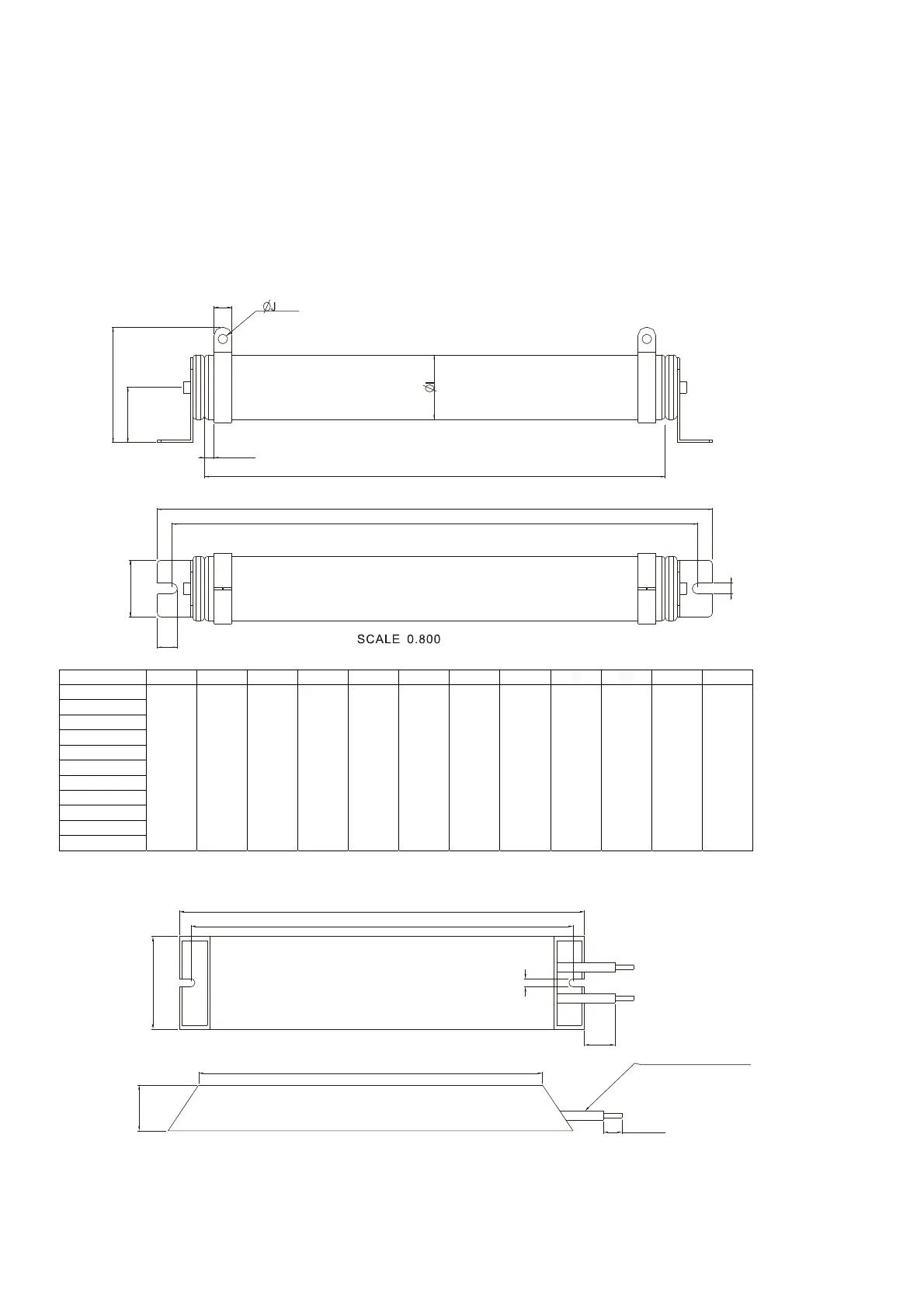
1. Specification and Appearance of Brake Resistors
1.1 Wire wound resistors: For 1000 W and above, refer to the following appearance of wire wound resistor
(Figure7-1) and its model and specification comparison table (Table 7-5) for details.
A
B
C
D
H
F
K
G
E
L
Figure 7-1
Models and Specifications Comparison Table of Wire Wound Resistors:
Unit: mm
Models A B C D E F G H
Ø ØJ K L
BR1K0W4P3
470±10 445±5 48±0.2 9.1±0.1 390±3 98±5 47±5 15±1 55±5 8.1±0.1 21±0.2 8±1
BR1K0W5P1
BR1K0W016
BR1K0W020
BR1K0W075
BR1K2W3P9
BR1K2W015
BR1K5W3P3
BR1K5W012
BR1K5W013
BR1K5W043
Table 7-5
1.2 Aluminum housed resistors: For below 1000 W, refer to the following appearance of aluminum-housed
resistor (Figure 7-2) and its model and specification comparison table (Table 7-6) for details
A
W
L1
L 2
L
H
L3
12.0
16A WG, 1. 31 8 M M2
Figure 7-2