Chapter 8 Option CardsC2000 Plus
8-37
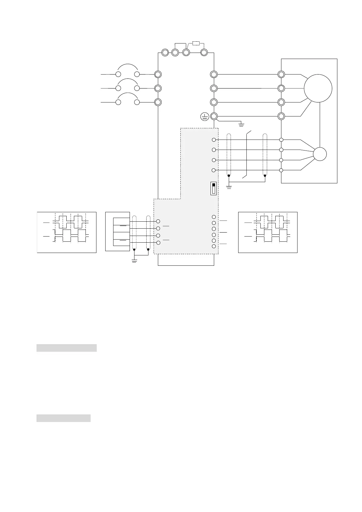
8-12-3 EMC-MC01 Wiring Diagram
NOTE: The current input voltage for Tamagawa encoder is +5V, ensure to switch to +5V before the
installation. The voltage +8V is reserved for the power demand of other encoders in the future.
8-12-4 Drive Setting
The following is the drive’s parameter setting when install EMC-MC01.
Example: Delta Servo Motor MSJ series 7 kW models (Model: MSJ-LA2070E42E):
Encoder Information
Signal Format: Tamagawa
Resolution: 17bit (Single-turn)
2
17
= 131072
131072 ÷ 4 = 32768
Parameter Setting
Refer to the following descriptions for more details.
Pr.10-00 = 8
Pr.10-01 = 32768
Pr.10-02 = 1
Y0
Y0
Y1
Y1
VP
DCM
DATA+
DATA-
AO
AO
ZO
BO
ZO
BO
A2
A2
B2
B2
U/T1
V/T2
W/T3
R/L1
S/L2
T/L3
R
S
T
Motor
M
-
+1
+2/B1
B2
U
V
W
AO
AO
BO
BO
Phase Difference 90°
Y0
Y0
Y1
Y1
Phase Difference 90°
Jumper
Braking Resistor (Optional)
Non-fuse Breaker
NFB
PG
Encoder
Ta ma ga wa
FSW1*
+5V
+8V
EMC-MC01