Chapter 2 InstallationC2000 Plus
2-4
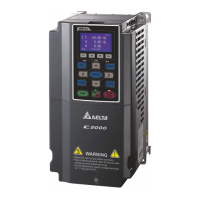
Frame A
VFD007C23A-21; VFD007C43A-21; VFD007C4EA-21; VFD015C23A-21; VFD015C43A-21;
VFD015C4EA-21; VFD015C53A-21; VFD022C23A-21; VFD022C43A-21; VFD022C4EA-21;
VFD022C53A-21; VFD037C23A-21; VFD037C43A-21; VFD037C4EA-21; VFD037C53A-21;
VFD040C43A-21; VFD040C4EA-21; VFD055C43A-21; VFD055C4EA-21
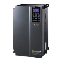
Frame B
VFD055C23A-21; VFD055C53A-21; VFD075C23A-21; VFD075C43A-21; VFD075C4EA-21;
VFD075C53A-21; VFD110C23A-21; VFD110C43A-21; VFD110C4EA-21; VFD110C53A-21;
VFD150C43A-21; VFD150C4EA-21; VFD150C53A-21
Frame C
VFD150C23A-21; VFD185C23A-21; VFD185C43A-21; VFD185C4EA-21; VFD185C63B-21;
VFD220C23A-21; VFD220C43A-21; VFD220C4EA-21; VFD220C63B-21; VFD300C43A-21;
VFD300C4EA-21; VFD300C63B-21; VFD370C63B-21
Frame D0
VFD370C43S-00; VFD370C43S-21; VFD450C43S-00; VFD450C43S-21
Frame D
VFD300C23A-00; VFD300C23A-21; VFD370C23A-00; VFD370C23A-21; VFD450C63B-00;
VFD450C63B-21; VFD550C43A-00; VFD550C43A-21; VFD550C63B-00; VFD550C63B-21;
VFD750C43A-00; VFD750C43A-21
Frame E
VFD450C23A-00; VFD450C23A-21; VFD550C23A-00; VFD550C23A-21; VFD750C23A-00;
VFD750C23A-21; VFD750C63B-00; VFD750C63B-21; VFD900C43A-00; VFD900C43A-21;
VFD900C63B-00; VFD900C63B-21; VFD1100C43A-00; VFD1100C43A-21;
VFD1100C63B-00; VFD1100C63B-21; VFD1320C63B-00; VFD1320C63B-21
Frame F
VFD900C23A-00; VFD900C23A-21; VFD1320C43A-00; VFD1320C43A-21;
VFD1600C43A-00; VFD1600C43A-21; VFD1600C63B-00; VFD1600C63B-21;
VFD2000C63B-00; VFD2000C63B-21
Frame G
VFD1850C43A-00; VFD1850C43A-21; VFD2000C43A-00; VFD2000C43A-21;
VFD2200C43A-00; VFD2200C43A-21; VFD2500C43A-00; VFD2500C43A-21;
VFD2500C63B-00; VFD2500C63B-21; VFD3150C63B-00; VFD3150C63B-21
Frame H
VFD2800C43A-00; VFD2800C43C-21; VFD3150C43A-00; VFD3150C43C-21;
VFD3550C43A-00; VFD3550C43C-21; VFD4000C43A-00; VFD4000C43C-21;
VFD4000C63B-00; VFD4000C63B-21; VFD4500C43A-00; VFD4500C43C-21;
VFD4500C63B-00; VFD4500C63B-21; VFD5000C43A-00; VFD5000C43C-21;
VFD5600C43A-00; VFD5600C43C-21; VFD5600C63B-00; VFD5600C63B-21;
VFD6300C63B-00; VFD6300C63B-21
Table 2-2
Figure 2-7
NOTE:
The mounting clearance stated in the figure is for installing the drive
in an open area. To install the drive in a confined space (such as
cabinet or electric box), follow the following rules: (1) Keep the
minimum mounting clearances. (2) Install a ventilation equipment
or an air conditioner to keep surrounding temperature lower than
operation temperature. (3) Refer to parameter setting and set up
Pr.00-16, Pr.00-17, and Pr.06-55.
The table below shows the heat dissipation and the required air
volume when installing a single drive in a confined space. When
installing multiple drives, the required air volume shall be multiplied
by the number of the drives.
Refer to the table below (Airflow Rate for Cooling) for ventilation
equipment design and selection.
Refer to the table below (Power Dissipation for AC Motor Drive) for
air conditioner design and selection.
Different control mode affects the derating. See Pr.06-55 for more
information.
Ambient temperature durating curve shows the dertaing status in
different temperature in relation to different protection level.
Refer to Section 9-7 for ambient temperature derating curve and
derating curves under different control modes.
If UL Type 1 models need side-by-side installation, remove the top
cover for Frame A–C. Do NOT install the conduit box for Frame D
and above.
 Loading...


