EasyManua.ls Logo

Delta C2000 Plus Series - Page 458

Delta C2000 Plus Series
1259 pages
To Next Page IconTo Next Page
To Previous Page IconTo Previous Page
Loading...
Chapter 12 Descriptions of Parameter SettingsC2000 Plus
12.1-01-9
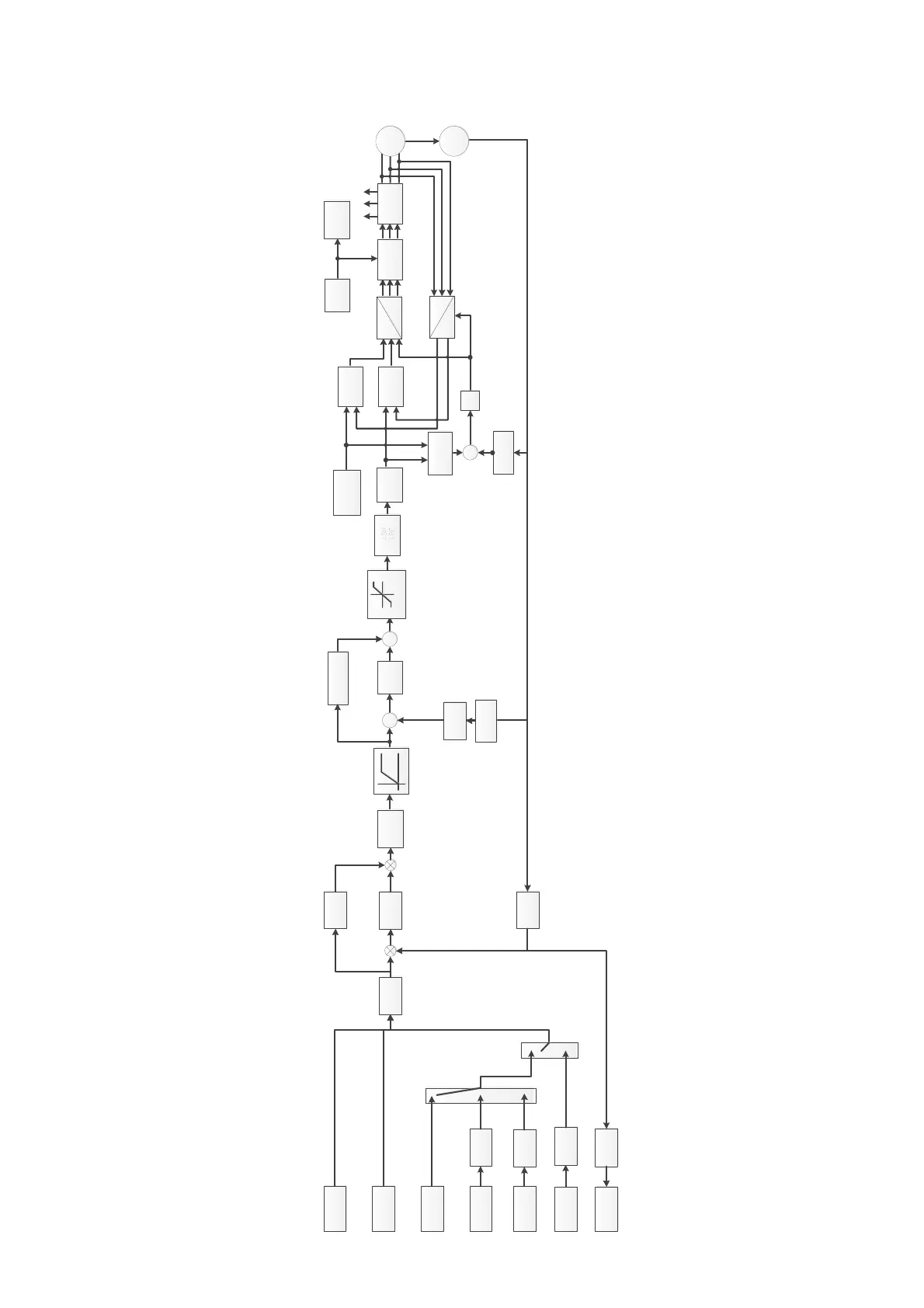
IMFOCPG position control diagram (Pr.00-10 = 1, and Pr.00-11 = 3):
Pr11-14
Torque limit
Pr11-17~11-20
ASR
control
Acc/Dec time
Pr01-12~01-27
-
+
Feedforward
control
Pr11-12
q-axis
current
calculator
IGBT
PWM
dq
abc
q-axis ACR
Speed
feedback
θ
e
ω
r
Pr01-01~01-02
Pr05-01~05-09
Active
magnetic
regulator
Slip
calculator
+
ω
sl
ʃ
+
d-axis ACR
Pr07-23
Encoder
Pr10-00~10-02
Pr11-21
Pr11-22
Pr10-35
Pr10-36
dq
abc
U
a
U
b
U
c
I
d
*
I
q
*
IM
I
a
I
b
I
c
DC bus
voltage
detection
DC bus
voltage
protection
Pr11-00 Bit0=0
set Pr11-06~11-11
Pr11-00 Bit0=1
set Pr11-03~11-05
+
+
ASR
LPF
Point-to-point
(P2P)
positioning
Pulse-train
positioning
Position command
source
Pr11-40
MI=1, 2, 3, 4, 88
Pr04-15 ~ 04-44
Route plan
APR
control
Feedforward
control
Pr11-24
Pr11-51 ~ 11-54
Pr11-25
Pr11-26
Pr11-43 ~ 11-45
Pr01-20 ~ 01-22
Pr01-46
Pr11-50
Pr11-56 ~ 11-59
Electrical gear
ratio A/B
Electrical gear
ratio A/B
Pulse output
Pr10-17/Pr10-18
Pr10-16
Homing
MI=44, 45, 46, 47
Pr11-68 ~ 11-74
Single-point
positioning
MI=35
Pr11-65, 11-66
Mechanical
gear ratio
A/B
CAN/Modbus/
communication
card
Pr10-04
Pr10-05
Pr10-06
Pr10-07
Electrical gear
ratio A/B
Pr10-17/Pr10-18
Position
record
PLC
PLC Command Mask
Pr00-19
Electrical gear
ratio A/B
Pr10-17/Pr10-18
Pr11-75
Pr11-76
ω
r
Mechanical
gear ratio
A/B
Pr10-04
Pr10-05
Pr10-06
Pr10-07
AVR
Speed
feedback

Table of Contents

Related product manuals