Chapter 12 Descriptions of Parameter SettingsC2000 Plus
12.1-09-2
5 : 7, O, 2 (ASCII)
6 : 8, N, 1 (ASCII)
7 : 8, N, 2 (ASCII)
8 : 8, E, 1 (ASCII)
9 : 8, O, 1 (ASCII)
10 : 8, E, 2 (ASCII)
11 : 8, O, 2 (ASCII)
12: 8, N, 1 (RTU)
13: 8, N, 2 (RTU)
14: 8, E, 1 (RTU)
15: 8, O, 1 (RTU)
16: 8, E, 2 (RTU)
17: 8, O, 2 (RTU)
Control by PC (Computer Link)
When using the RS-485 serial communication interface, you must specify each drive’s
communication address in Pr.09-00. The computer then implements control using the drives’
individual addresses.
Modbus ASCII (American Standard Code for Information Interchange): Each byte of data is the
combination of two ASCII characters. For example, one byte of data: 64 Hex, shown as ‘64’ in
ASCII, consists of ‘6’ (36Hex) and ‘4’ (34Hex).
09-09
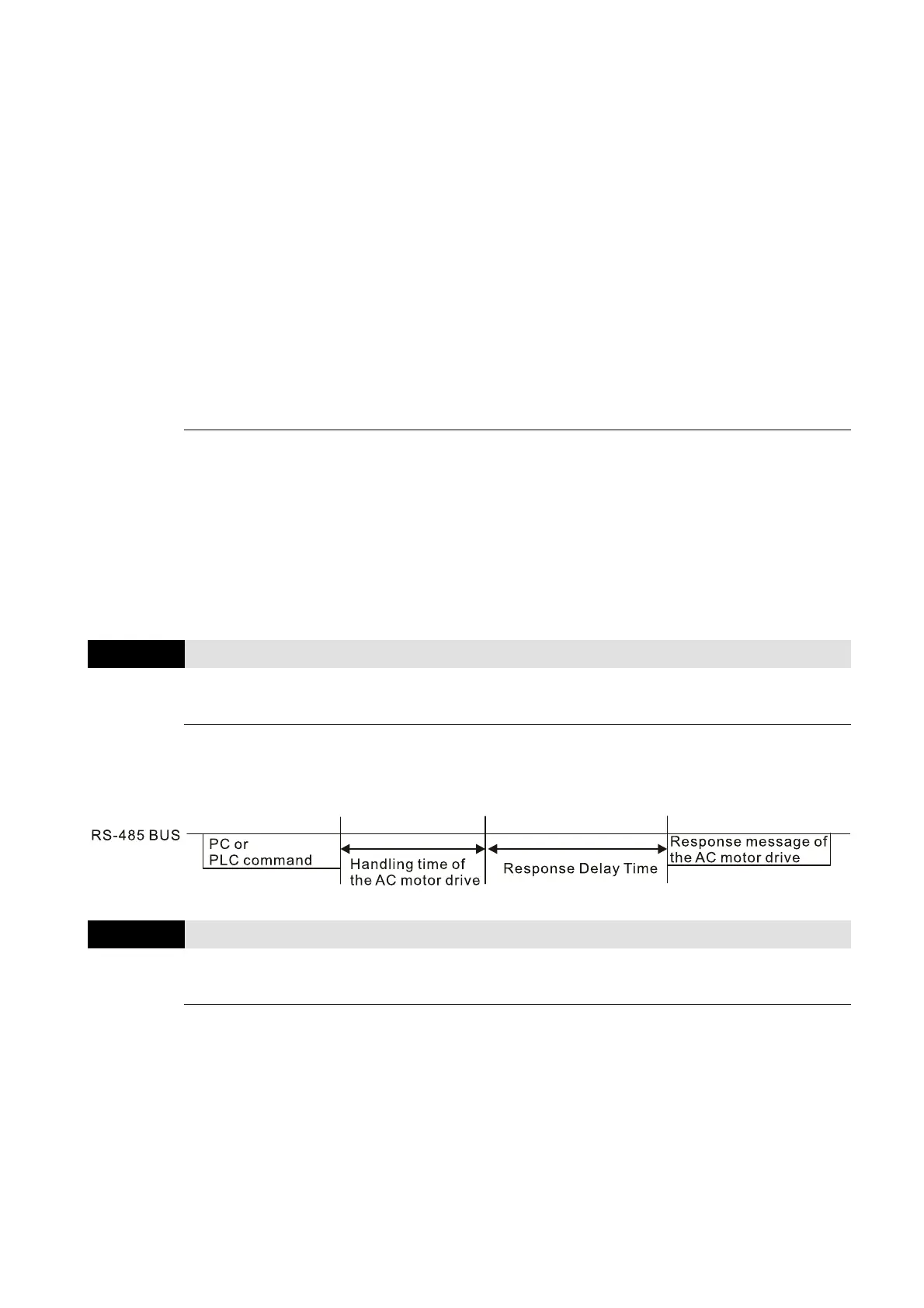
Modbus Communication Response Delay Time
Default: 2.0
Settings 0.0–200.0 ms
If the host controller does not finish the transmitting / receiving process, you can use this
parameter to set the response delay time after the AC motor drive receives communication
command as shown in the following picture.
09-10
Communication Main Frequency
Default: 60.00
Settings 0.00–599.00 Hz
When you set Pr.00-20 to 1 (RS-485 serial communication input), the AC motor drive saves the
last Frequency command into Pr.09-10 when there is abnormal power off or momentary power
loss. When power is restored, the AC motor drive operates with the frequency in Pr.09-10 if no
new Frequency command input. When a Frequency command of RS-485 changes (the
frequency command source must be set as Modbus), this parameter also changes.