Chapter 5 Main Circuit TerminalsC2000 Plus
5-2
Tighten the screws in the main circuit terminal to prevent sparks caused by screws
loosened due to vibration.
If necessary, use an inductive filter only at the motor output terminals U/T1, V/T2,
W/T3 of the AC motor drive. DO NOT use phase-compensation capacitors or L-C
(Inductance-Capacitance) or R-C (Resistance-Capacitance), unless approved by
Delta.
DO NOT connect phase-compensation capacitors or surge absorbers at the output
terminals of AC motor drives.
DO NOT short circuit [+1, -], [+2, -], [+1/DC+, -/DC-] or connect brake resistors directly
to any of them to prevent damage to the drive or to the brake resistors.
Ensure proper insulation of the main circuit wiring in accordance with the relevant
safety regulations.
Main input power terminals
Do not connect three-phase model to single-phase power. R/L1, S/L2 and T/L3 have
no phase-sequence requirement; they can be connected in any sequence.
Add a magnetic contactor (MC) to the power input wiring to cut off power quickly and
reduce malfunctions when the AC motor drive protection function activates. Both ends
of the MC should have an R-C surge absorber.
Use voltage and current within the specifications in Chapter 09. Refer to Chapter 09
Specifications for details.
When using a general GFCI (Ground Fault Circuit Interrupter), select a current sensor
with sensitivity of 200 mA or above and not less than 0.1-second operation time to
avoid nuisance tripping.
Use shielded wire or conduit for the power wiring and ground the two ends of the
shield wire or conduit.
DO NOT run and stop the AC motor drives by turning the power ON and OFF. Run
and stop the AC motor drives by sending RUN and STOP commands through the
control terminals or the keypad. If you still need to run and stop the AC motor drives by
turning the power ON and OFF, do so no more often than ONCE per hour.
To comply with UL standards, connect the drive to a three-phase three-wire or
three-phase four-wire Wye system type of mains power system.
Output terminals of the main circuit
Use well-insulated motor, suitable for inverter operation.
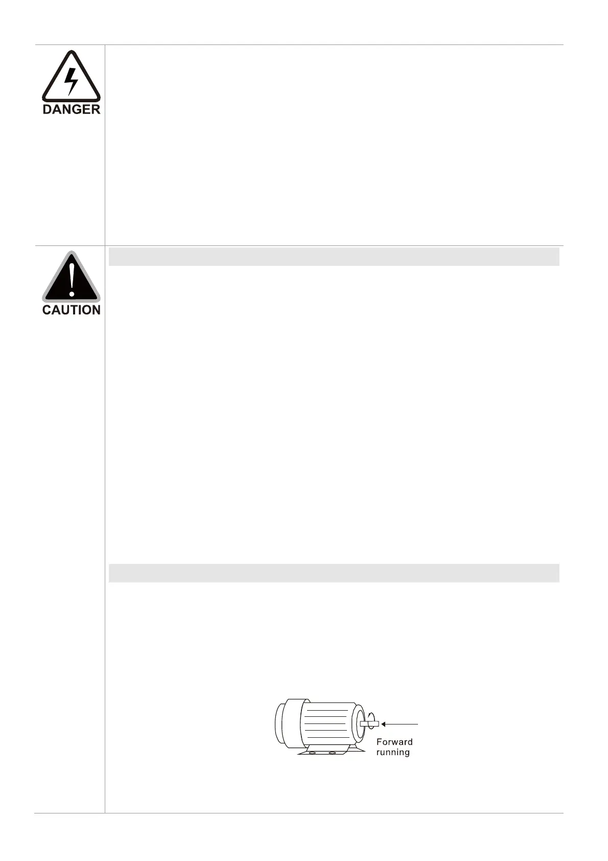
When the AC drive output terminals U/T1, V/T2, and W/T3 are connected to the motor
terminals U/T1, V/T2, and W/T3 respectively, the motor will rotate counterclockwise
(as viewed on the shaft end of the motor, refer to the pointed direction in the figure
below) upon a forward operation command is received. To permanently reverse the
direction of motor rotation, switch over any of the two motor leads.
Figure 5-1