1.3 LED Indicators
Name Indicator Status Indication
RUN Green
On Normal status
Blink
Pre-operation (on / off 200 ms)
Safe mode (on 200 ms / off 1000 ms)
Off Initial status
ERROR Red
Blink
Basic configuration error (on / off 200 ms)
Status switch error
(on 200 ms / off 1000 ms)
Time-out (on 200 ms twice / off 1000 ms)
Off No error
IN LINK Green
On Network connected
Blink Network in operation
Off Network not connected
OUT LINK Green
On Network connected
Blink Network in operation
Off Network not connected
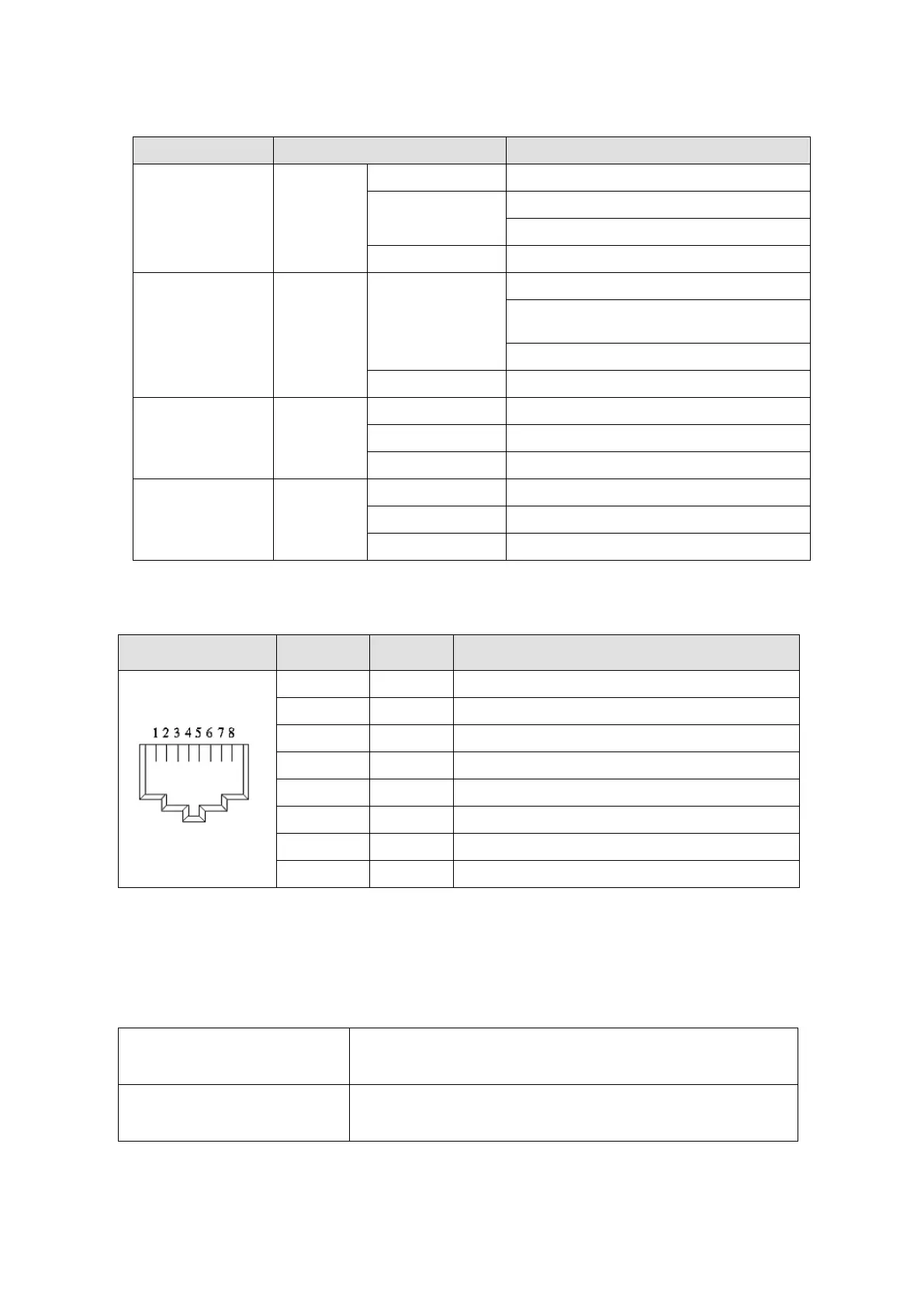
1.4 RJ45 PIN Definition
RJ45 Diagram PIN # Definition Description
1 Tx+ Positive pole for data transmission
2 Tx- Negative pole for data transmission
3 Rx+ Positive pole for data reception
4 -- N / C
5 -- N / C
6 Rx- Negative pole for data reception
7 -- N / C
8 -- N / C
1.5 Application
1.5.1 Applicable firmware version and supporting mode
Applicable motor drive
firmware version
MS300 V1.07 / MH300 V1.02or later
Communication card firmware
version
CMM-EC02 V1.01 or later
NOTE: This user manual applies to MH300 and MS300 (hereafter referred to as “M300 series”).
Send Quote Requests to info@automatedpt.com
Call +1(800)985-6929 To Order or Order Online At Deltaacdrives.com
Send Quote Requests to info@automatedpt.com
Call +1(800)985-6929 To Order or Order Online At Deltaacdrives.com