Chapter 7 Optional AccessoriesCP2000
7-37
Following table is the THDi value of Delta motor drive matching AC/DC reactors:
Current
harmonic
Models without built-in DC reactor Models with built-in DC reactor
No AC/DC
reactor
3% input AC
reactor
5% input AC
reactor
4% DC
reactor
No input
AC
reactor
3% input AC
reactor
5% input AC
reactor
5
th
73.3% 38.5% 30.8% 25.5% 31.16% 27.01% 25.5%
7
th
52.74% 15.3% 9.4% 18.6% 23.18% 9.54% 8.75%
11
th
7.28% 7.1% 6.13% 7.14% 8.6% 4.5% 4.2%
13
th
0.4% 3.75% 3.15% 0.48% 7.9% 0.22% 0.17%
THDi 91% 43.6% 34.33% 38.2% 42.28% 30.5% 28.4%
Note THDi may have some difference due to different installation conditions (like wires or motors) and environment.
AC Output Reactor
When using drives in long wiring output application, ground fault (GFF), over-current (oc) and motor
over-voltage (ov) often occur. GFF and oc cause errors due to the drive’s self-protective mechanism;
over-voltage damages motor insulation.
The excessive length of the output wires makes the grounded stray capacitance too large, increase
the three-phase output common mode current, and the reflected wave of the long wires makes the motor
dv / dt and the motor terminal voltage too high. Thus, installing a reactor on the drive’s output side can
increase the high-frequency impedance to reduce the dv / dt and terminal voltage to protect the motor.
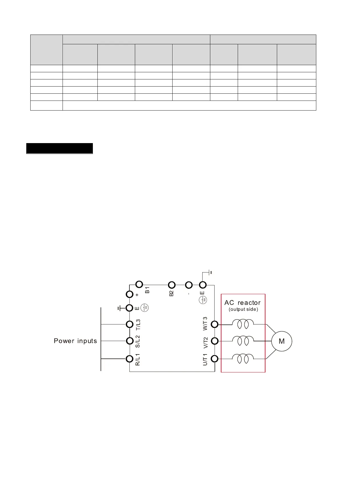
Installation
Install an AC output reactor in series between the three output phases U V W and the motor, as
shown in the figure below:
Wiring of AC output reactor
Table 7-45
Figure 7-26

 Loading...


