Chapter 12 Description of Parameter SettingsCP2000
12.1-03-19
Example 1, AFM2 0–10 V is set to the output frequency, the output equation is:
10 V * (output frequency / Pr.01-00) * Pr.03-24 + 10 V * Pr.03-27
Example 2, AFM2 0–20 mA is set to the output frequency, the output equation is:
20 mA*(output frequency / Pr.01-00) * Pr.03-24 + 20 mA * Pr.03-27
Example 3, AFM2 4–20 mA is set to the output frequency, the output equation is:
4 mA+16 mA * (output frequency / Pr.01-00) * Pr.03-24 + 16 mA * Pr.03-27
This parameter sets the corresponding voltage for the analog output 0.
AVI1 Terminal Input Selection
Default: 0
Settings 0: 0–10 V
1: 0–20 mA
2: 4–20 mA
ACI Terminal Input Selection
Default: 0
Settings 0: 4–20 mA
1: 0–10 V
2: 0–20 mA
When you change the input mode, verify that the external terminal switch (SW3, SW4)
corresponds to the setting for Pr.03-28–Pr.03-29.
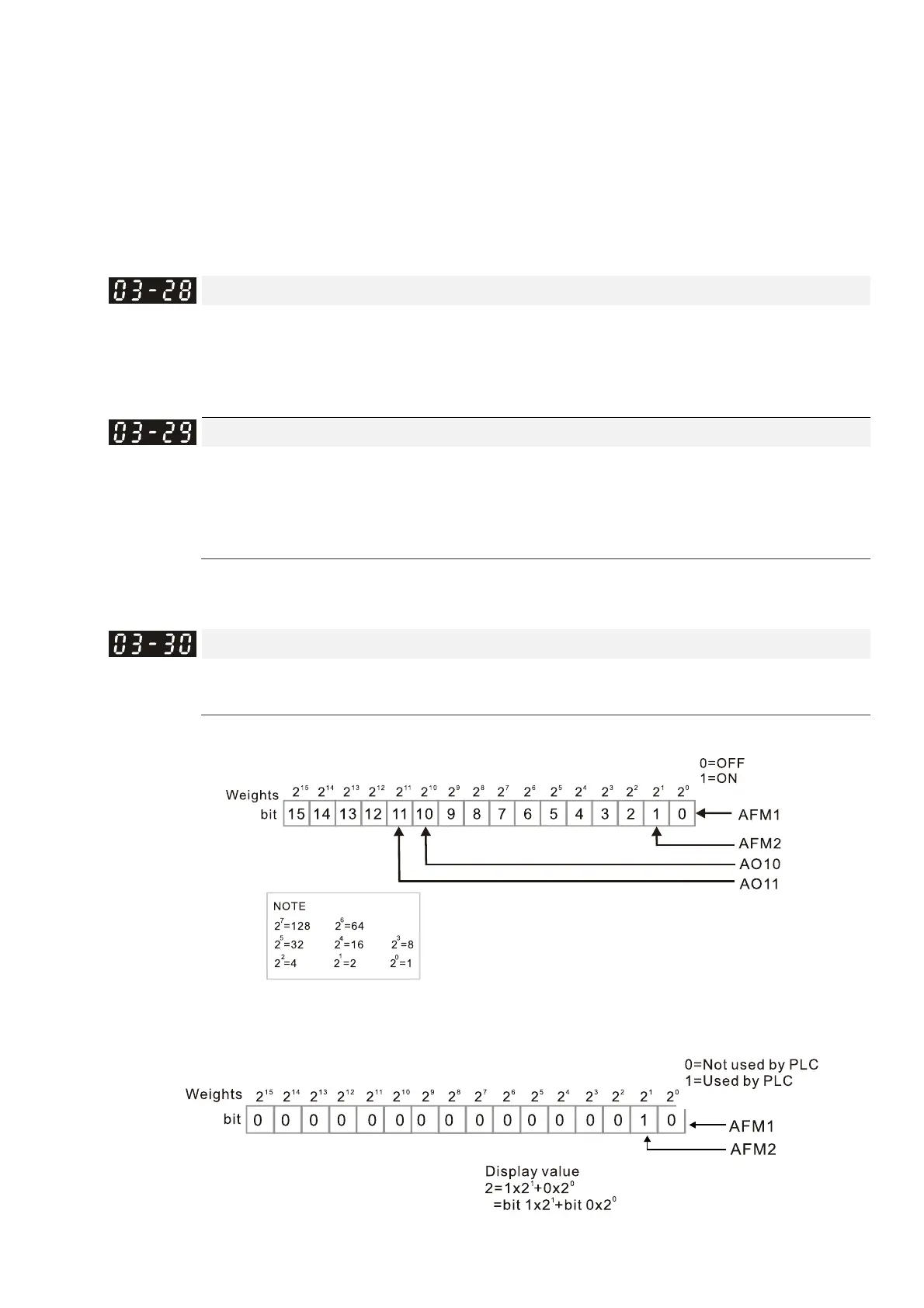
PLC Analog Output Terminal Status
Default: Read only
Settings Monitor the status of PLC analog output terminals
P.03-30 displays the external multi-function output terminal that used by PLC.
For Example:
When Pr.03-30 displays 0002h (hex), it means that AFM2 is used by PLC.
 Loading...


