Chapter 12 Description of Parameter SettingsCP2000
12.1-06-28
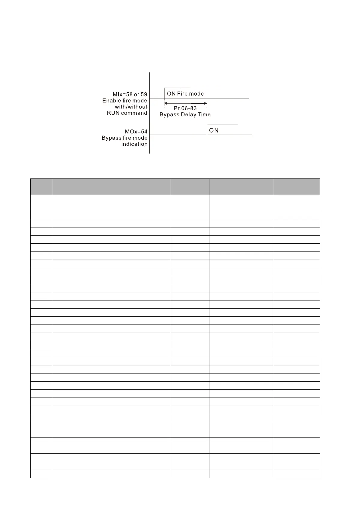
(2) When operating in fire mode, if there is an error on auto-reset and the number of times to
auto-reset remains zero or the fire alarm rings according to the time setting for Pr.06-83, then the
bypass function is enabled. MFO bypass indication is ON. If the auto-reset is successful before
the bypass function is enabled, the bypass delay counter returns to zero to wait for next trigger.
Table 1: Error detection under Normal mode, Fire mode and Bypass function in Fire mode.
(V means detectable)
Code Error name
Normal
mode
Fire Mode
Enable bypass
function
1 Over-current during acceleration (ocA) V(RS) V(able to auto-reset) V
2 Over-current during deceleration (ocd) V(RS) V(able to auto-reset) V
3 Over-current during constant speed (ocn) V(RS) V(able to auto-reset) V
4 Ground Fault (GFF) V V(able to auto-reset) V
5 IGBT short circuit (occ) V(RS) V(able to auto-reset) V
6 Over-current during stop (ocS) V(RS) V(able to auto-reset) V
7 Over-voltage during acceleration (ovA) V(RS) V(able to auto-reset) V
8 Over-voltage during deceleration (ovd) V(RS) V(able to auto-reset) V
9 Over-voltage during constant speed (ovn) V(RS) V(able to auto-reset) V
10 Over-voltage during stop (ovS) V(RS) V(able to auto-reset) V
11 Low-voltage during acceleration (LvA) V Not-detectable Not-detectable
12 Low-voltage during deceleration (Lvd) V Not-detectable Not-detectable
13 Low-voltage during constant speed (Lvn) V Not-detectable Not-detectable
14 Low-voltage during Stop (LvS) V Not-detectable Not-detectable
15 Input phase loss (OrP) V V(able to auto-reset) V
16 Over-heat 1 (oH1) V V(able to auto-reset) V
17 Over-heat 2 (oH2) V V(able to auto-reset) V
18 Thermistor 1 open (tH1o) V V(able to auto-reset) V
19 Thermistor 2 open (tH2o) V V(able to auto-reset) V
21 Over-load (oL) (150% 1Min, Inverter) V Not-detectable Not-detectable
22 Motor 1 over load (EoL1) V Not-detectable Not-detectable
23 Motor 2 over load (EoL2) V Not-detectable Not-detectable
24 Over heat 3 (oH3) V V(able to auto-reset) V
26 Over torque 1 (ot1) V Not-detectable Not-detectable
27 Over torque 2 (ot2) V Not-detectable Not-detectable
28 Low current (uC) V Not-detectable Not-detectable
30 EEPROM write error (cF1) V Not-detectable Not-detectable
31 EEPROM read error (cF2) V V Not-detectable
33
U phase current sensor detection error
(cd1)
V V Not-detectable
34
V phase current sensor detection error
(cd2)
V V Not-detectable
35
W phase current sensor detection error
(cd3)
V V Not-detectable
36 Clamp current detection error (Hd0) V V Not-detectable

 Loading...


