Chapter 12 Description of Parameter SettingsCP2000
12.1-07-3
Setting 1: Frequency tracking begins before momentary power loss and accelerates to the
master Frequency command after the drive output frequency and motor rotator speed are
synchronous. Use this setting when there is a lot of inertia with little resistance on the motor load.
For example, in equipment with a large inertia flywheel, there is NO need to wait until the
flywheel stops completely after a restart to execute the operation command; therefore, it saves
time.
Setting 2: Frequency tracking starts from the minimum output frequency and accelerates to the
master Frequency command after the drive output frequency and motor rotator speed are
synchronous. Use this setting when there is little inertia and large resistance.
This function is only valid when the RUN command is enabled.
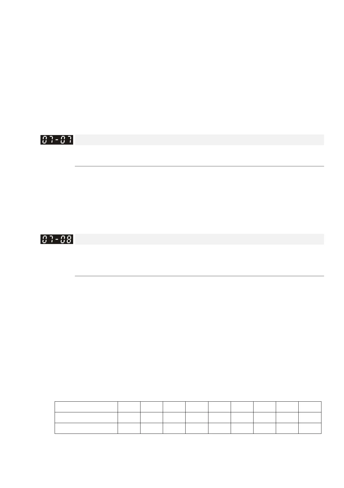
Allowed Power Loss Duration
Default: 2.0
Settings 0.0–20.0 sec.
Determines the maximum time of allowable power loss. If the duration of a power loss exceeds
this parameter setting, the AC motor drive stops output.
Pr.07-06 is valid when the maximum allowable power loss time is ≤ 20 seconds and the AC
motor drive displays “Lv”. If the AC motor drive is powered off due to overload, even if the
maximum allowable power loss time is ≤ 20 seconds, the operation mode set in Pr.07-06 does
not execute.
Base Block Time
Default: Depending on the
model power
Settings 0.0–5.0 sec. (Depending on the model power)
When momentary power loss is detected, the AC motor drive blocks its output and then waits for
a specified period of time (determined by Pr.07-08, called Base Block Time) before resuming
operation. Set this parameter to the time that allows the residual regeneration voltage at the
output side to decrease to 0V before activating the drive again.
This parameter is not only for the B.B. time, but also is the re-start delay time after free run.
The RUN command during a free run operation is memorized, and runs or stops with the last
frequency command after the delay time.
This delay time is only applicable in “Re-start after coast to stop” status, and does not limit ramp
to stop. The coast to stop can be caused by various control command source, or by errors.
Following table is the recommended setting for re-start delay time of each model power. You
must set Pr. 07-08 according to this table (the default of each model power is based on this table
as well).
kW 007 015 022 037 040 055 075 110 150
HP 1 2 3 5 5.5 7.5 10 15 20
Delay time (sec.) 0.3 0.4 0.5 0.6 0.7 0.7 0.8 0.9 1

 Loading...


