Chapter 12 Description of Parameter SettingsCP2000
12.1-13-3
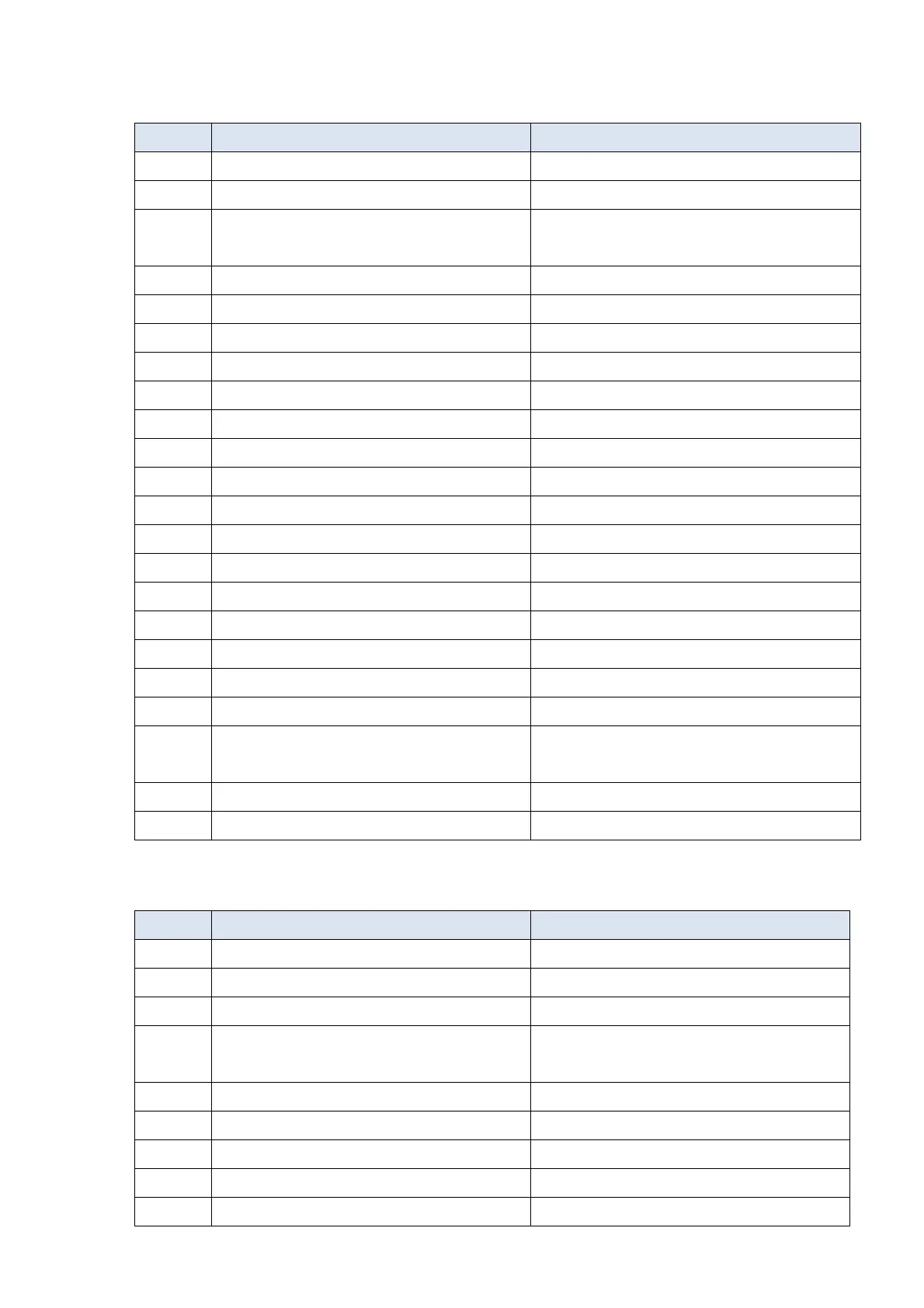
Group setting 04: Pump
The following table lists the relevant pump setting application parameters.
Pr. Explanation Settings
00-11 Speed control mode 0 (V/F mode)
00-16 Load selection 0: Light load
00-20
Master frequency command source (AUTO)
/ Source selection of the PID target
2: External analog input
00-21 Operation command source (AUTO) 1: External terminals.
00-23 Control of motor direction 1: Disable reverse
01-00 Maximum operation frequency Default setting
01-01 Output frequency of motor 1 Default setting
01-02 Output voltage of motor 1 Default setting
01-03 Mid-point frequency 1 of motor 1 Default setting
01-04 Mid-point voltage 1 of motor 1 Default setting
01-05 Mid-point frequency 2 of motor 1 Default setting
01-06 Mid-point voltage 2 of motor 1 Default setting
01-07 Minimum output frequency of motor 1 Default setting
01-08 Minimum output voltage of motor 1 Default setting
01-10 Output frequency upper limit 50 (Hz)
01-11 Output frequency lower limit 35 (Hz)
01-12 Acceleration time 1 15 (s)
01-13 Deceleration time 1 15 (s)
01-43 V/F curve selection 2: 2
nd
V/F curve
07-06 Restart after momentary power loss
2: Speed tracking by minimum output
frequency
07-11 Number of times of restart after fault
5 (times)
07-33 Auto-restart interval of fault
60 (s)
Group setting 10: Air Handling Unit, AHU
The following table lists the relevant AHU setting application parameters.
Pr. Explanation Settings
00-04 Content of multi-function display 2
00-11 Speed control mode 0 (V/F control)
00-16 Load selection 0: Light load
00-20
Master frequency command source (AUTO)
/ Source selection of the PID target
2 or 0 (External analog input)
00-21 Operation command source (AUTO) 1 or 0 (External terminals)
00-22 Stop method 1: Coast to stop
00-23 Control of motor direction 1: Disable reverse
00-30 Master frequency command (HAND) source 0: Digital keypad
00-31 Operation command (HAND) source 0: Digital keypad

 Loading...


