Chapter 5 Main Circuit TerminalsCP2000
5-10
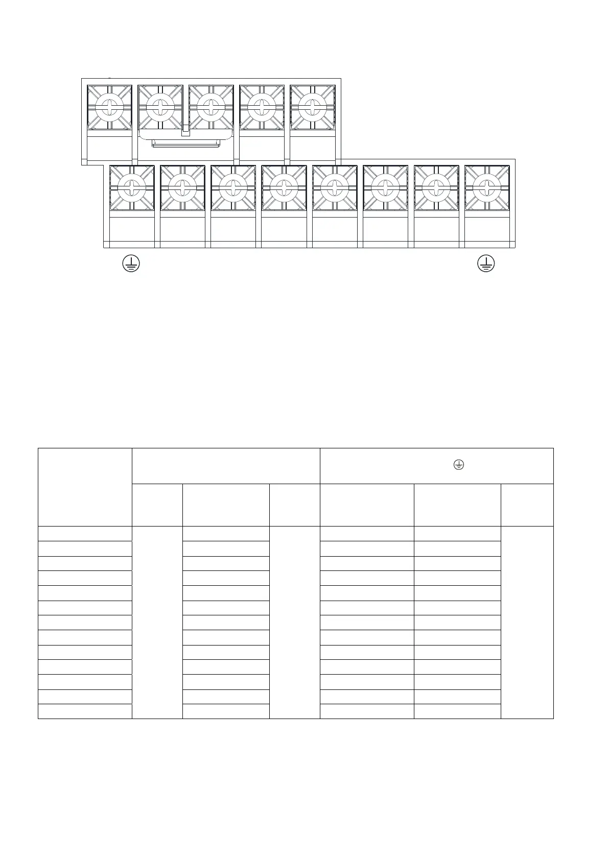
Frame B
-/DC- +
/DC+ +1/DC+ B1 B
R/L1 S/L2 T/L3 U/T1 V/T2 W/T3
If you install at Ta 40°C environment, please select copper wire with voltage rating 600V and
temperature resistant at 75°C or 90°C.
If you install at Ta 40°C above environment, please select copper wire with voltage rating 600V and
temperature resistant at 90°C or above.
For VFD150CP23A-21, if you install at Ta 30°C above environment, please select copper wire with
voltage rating 600V and temperature resistant at 90°C or above.
For UL installation compliant, please use copper wires for installation, the wire gauge is based on
temperature resistant at 75°C which is requested and recommended from UL. Do not reduce the
wire gauge when using higher temperature wire.
Wire fix to pole +2/DC+ and +1/DC+: 45 kg-cm / [39.0 lb-in] / [4.42 Nm] (±10%)
Model Name
Main Circuit Terminals
R/L1, S/L2, T/L3, U/T1, V/T2, W/T3, B1,
B2, -/DC-, +2/DC+, +1/DC+
Terminal
Max. Wire
Gauge
Min. Wire Gauge
Screw
Spec. and
Torque
(±10%)
Max. Wire Gauge Min. Wire Gauge
Screw
Spec. and
Torque
(±10%)
VFD075CP23A-21
25 mm
2
[4 AWG]
10 mm
2
[8 AWG]
M5
35kg-cm
[30.4lb-in.]
[3.43Nm]
10 mm
2
[8 AWG] 10 mm
2
[8 AWG]
M5
35kg-cm
[30.4lb-in.]
[3.43Nm]
VFD110CP23A-21 25 mm
2
[4 AWG] 25 mm
2
[4 AWG] 16 mm
2
[6 AWG]
VFD150CP23A-21 25 mm
2
[4 AWG] 25 mm
2
[4 AWG] 16 mm
2
[6 AWG]
VFD110CP43B-21 10.0 mm
2
[8 AWG] 10.0 mm
2
[8 AWG] 10.0 mm
2
[8 AWG]
VFD150CP43B-21 10.0 mm
2
[8 AWG] 10.0 mm
2
[8 AWG] 10.0 mm
2
[8 AWG]
VFD185CP43B-21 16 mm
2
[6 AWG] 16 mm
2
[6 AWG] 16 mm
2
[6 AWG]
VFD110CP4EB-21 10.0 mm
2
[8 AWG] 10.0 mm
2
[8 AWG] 10.0 mm
2
[8 AWG]
VFD150CP4EB-21 10.0 mm
2
[8 AWG] 10.0 mm
2
[8 AWG] 10.0 mm
2
[8 AWG]
VFD185CP4EB-21 16 mm
2
[6 AWG] 16 mm
2
[6 AWG] 16 mm
2
[6 AWG]
VFD055CP53A-21 6 mm
2
[10 AWG] 6 mm
2
[10 AWG] 6 mm
2
[10 AWG]
VFD075CP53A-21 6 mm
2
[10 AWG] 6 mm
2
[10 AWG] 6 mm
2
[10 AWG]
VFD110CP53A-21 10 mm
2
[8 AWG] 10 mm
2
[8 AWG] 10 mm
2
[8 AWG]
VFD150CP53A-21 10 mm
2
[8 AWG] 10 mm
2
[8 AWG] 10 mm
2
[8 AWG]
 Loading...


