Chapter 4 Installation & Wiring
38
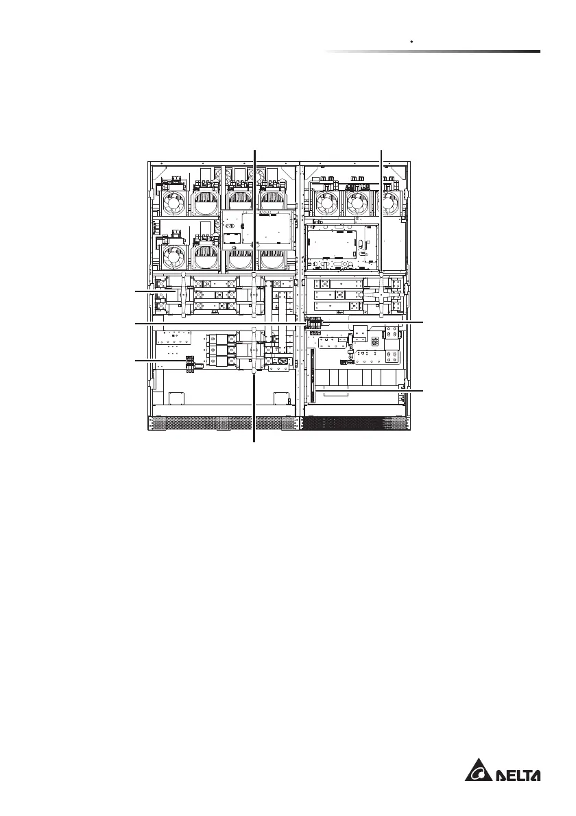
Figure 4-33 Front view with door open: seven fuses, four switches, one SMART
slot, and communication interfaces (NT-Q board).
UPS output
switch
Manual
bypass switch
SMART slot
Reserve
input switch
Fuses
(From left to right)
1. Inverter’s
transformer
fan fuse
2. Static switch’s
heat sink fan fuse
3. Inverter’s heat
sink fan fuse
Communication
interfaces
(NT-Q board)
Rectifier
input switch
Fuses
(From left to right)
1. Rectifier’s
transformer
fan fuse
2. Rectifier’s
heat-sink
fan fuse
3. PCB power fuse
4. Power fuse
Figure 4-33
4.4 Installation Environment and Safety Precaution
To ensure UPS normal operation, prolong UPS lifetime, and protect UPS from
disorder and malfunction, the user should select an optimal installation location and
environment according to the following safety instructions.
1. Install the UPS indoors. Do not place it outdoors.
7KHZHLJKWRIWKH836LVFRQFHQWUDWHGRQDUHODWLYHO\VPDOOÀRRUDUHDGXHWRWKH
FDELQHWGHVLJQ7KHLQVWDOODWLRQORFDWLRQPXVWWKHUHIRUHKDYHDVXႈFLHQWÀRRU
loading capacity to bear the weight of the UPS.
3. The UPS and battery cabinet should be located on enough space for
maintenance and good ventilation.
 Loading...