Appendix B Accessories|VFD-B-P Series
B-18 Revision April 2009, SW V1.00
3. 7.5hp (5.5kW) and above
P
G
-
0
2
C
o
n
tr
o
l B
o
a
r
d
P
l
a
s
t
i
c
s
t
a
n
d
o
f
f
P
G
c
a
rd
te
r
m
i
n
a
l
Insulation
spacer
B.3.1.1 PG Card and Pulse Generator (Encoder)
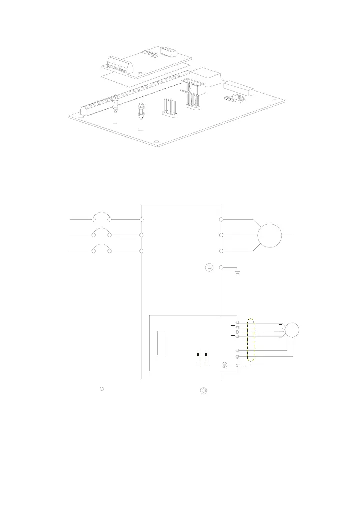
1. Basic Wiring Diagram
R/L1
S/L2
T/L3
NFB
U/T1
V/T2
W/T3
IM
3~
Motor
PG
A
B
DCM
PG-02
V
F
D-B-P
VP
+12V
GND
A
B
OC
5V
TP
12V
Factory
Setting
PG-02 and Pulse Generator Connections
Pulse Generator
Output 12V DC
A
B
A
B
R/L1
S/L2
T/L3
None fused breake
E
Main circui t (power) terminals
Control circuit terminals

 Loading...


