Appendix B Accessories|VFD-B-P Series
Revision April 2009, SW V1.00 B-19
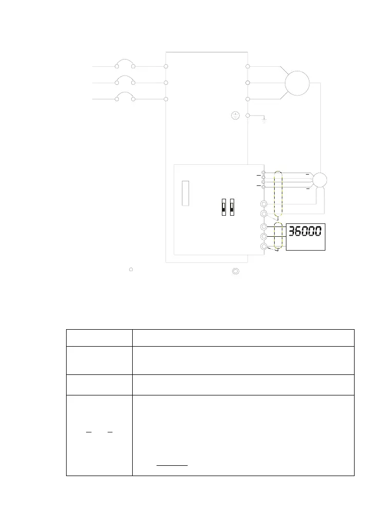
2. Basic Wiring Diagram with RPM Meter Attached.
R/L1
S/L2
T/L3
NFB
U/T1
V/T2
W/T3
IM
3~
Motor
VP
COM
PG-02
VFD-B-P
+5V
GND
OC
5V
TP
12V
PG-02 and Pulse Generator Connections
A/O
B/O
RPM meter
DCM
PG
A
B
A
B
A
B
A
B
R/L1
S/L2
T/L3
None fused breaker
Main circuit (power) terminals
Control circuit terminals
B.3.1.2 PG-02 Terminal Descriptions
1. Terminals
Terminal Symbols Descriptions
VP
Power source of PG-02 (FSW1 can be switched to 12V or 5V)
Output Voltage: (+12VDC ±5% 200mA) or (+5VDC ±2% 400mA)
DCM
Power source (VP) and input signal (A, B) common
A-
,B-
B
Input signal from Pulse Generator. Input type is selected by FSW2. It
can be 1-phase or 2-phase input. Maximum 500kP/sec (z-phase
function is reserved). If the voltage exceeds 12V, it needs to use TP
type with connecting the external current limiting resistor(R). The
current should be within 5 to 15mA.
The formal of current limiting resistor is:
mA
R
VVin
mA 15
480
2
5 ≤
+Ω
≤

 Loading...


