Appendix B Accessories|VFD-B-P Series
B-20 Revision April 2009, SW V1.00
Terminal Symbols Descriptions
A/O, B/O
PG-02 output signal for use with RPM Meter. (Open Collector)
Maximum DC24V 300mA
COM
PG-02 output signal (A/O, B/O) common.
2. Wiring Notes
The control, power supply and motor leads must be laid separately. They must not be fed
through the same cable conduit / trunk.
a. Please use a shielded cable to prevent interference. Do not run control wires
parallel to any high voltage AC power line (200 V and above).
b. Connect shielded wire to DCM
only.
c. Recommended wire size 0.21 to 0.81mm
2
(AWG24 to AWG18).
d. Wire length:
Types of Pulse
Generators
Maximum Wire Length Wire Gauge
Output Voltage 50m
Open Collector 50m
Line Driver 300m
Complementary 70m
1.25mm
2
(AWG16) or above
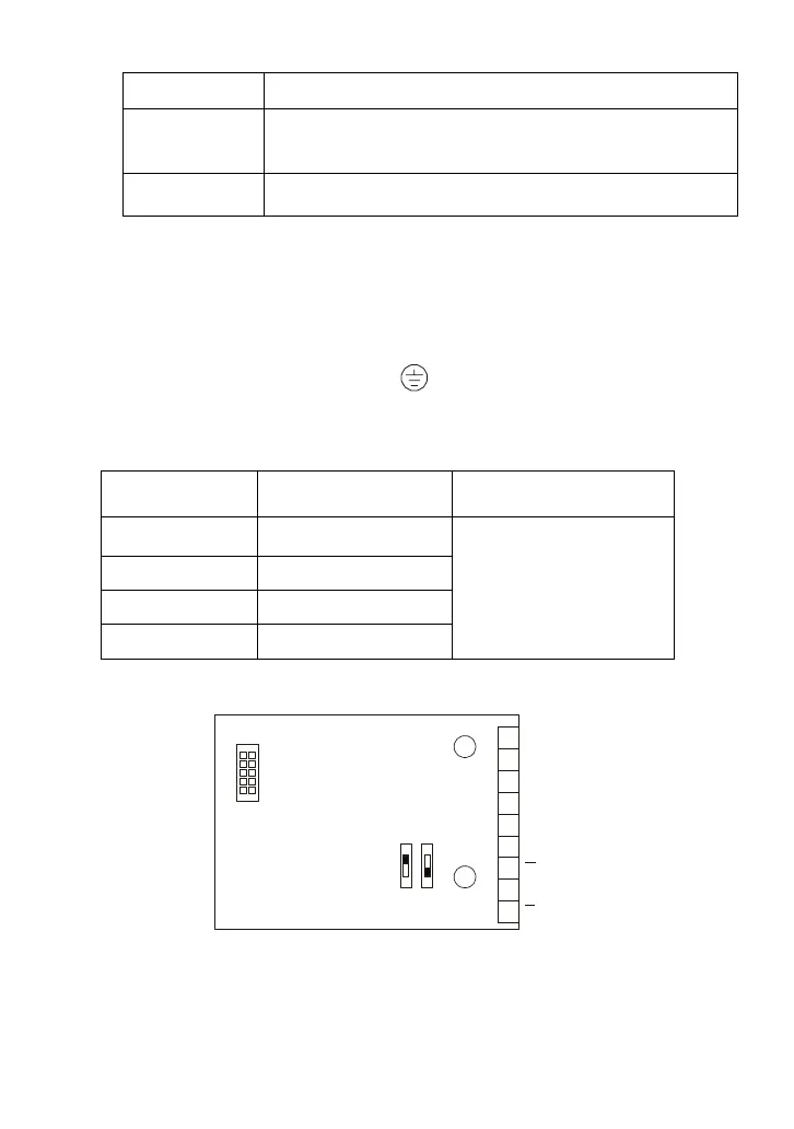
3. Control Terminals Block Designations.
OC
5V
TP
12V
A/O
B/O
COM
VP
DCM
A
B
PG-02
FSW2 FSW1
Connect to VFD-B
series control board
Wiring Terminals
Select the power
source and output
of Pulse Generator
A
B
4. Types of Pulse Generators (Encoders)

 Loading...


