Appendix B Accessories|VFD-B-P Series
Revision April 2009, SW V1.00 B-23
3. 7.5HP (5.5kW) and above
P
G
-
0
3
c
o
n
t
r
o
l
b
o
a
r
d
p
l
as
t
i
c
s t
an
d
o
f
f
P
G
c
a
r
d
t
e
r
m
i
n
a
l
insulation
spacer
B.3.2.2 PG Card and Pulse Generator (Encoder)
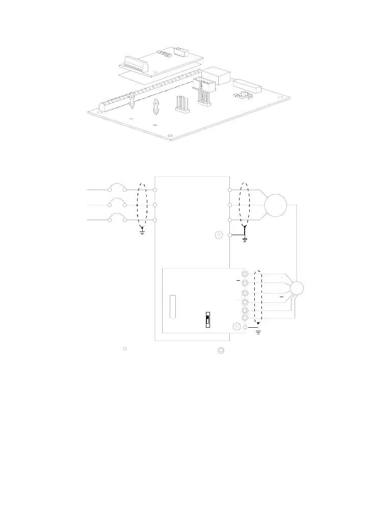
1. Basic wiring diagram
Non-Fuse Breake
NFB
R/L1
S/L2
T/L3
U/T1
V/T2
W/T3
M
3~
Motor
PG
A
B
12V
0V
PG-03
+12V
GND
OC
TP
Factory
Se tting
C onne ct io n between P G- 03 an d th e Enc ode
*S pe cification of th e Enco der
is of the 12V/OC Output
A
B
A
B
A
B
Shield
Te rmi na l
R/L1
S/L2
T/L3
Main circuit (power) terminals
Control circuit terminals
VFD-B-P

 Loading...


