Chapter 4 Parameters|VFD-EL-W
135
to improve the system state. Using a suitable differential time can reduce overshoot and shorten
adjustment time; however, the differential operation increases noise interference. Note that a too
large differential causes more noise interference. In addition, the differential shows the change
and the differential output is 0 when there is no change. Note that you cannot use the differential
control independently. You must use it with the other two controllers for the PD controller or PID
controller.
Sets the D controller gain to determine the deviation change response. Using a suitable
differential time reduces the P and I controllers overshoot to decrease the oscillation for a stable
system. A differential time that is too long may cause system oscillation.
The differential controller acts on the change in the deviation and cannot reduce the
interference. Do not use this function when there is significant interference.
Upper Limit of Integral Control
Defines an upper bound for the integral gain (I) and therefore limits the master frequency. The
formula is: Integral upper bound = Maximum Operation Frequency (Pr.01.00) × (Pr.10.05 %).
An excessive integral value causes a slow response due to sudden load changes and may
cause motor stall or machine damage. If so, decrease it to a proper value.
The PID delay output reduces the system oscillation.
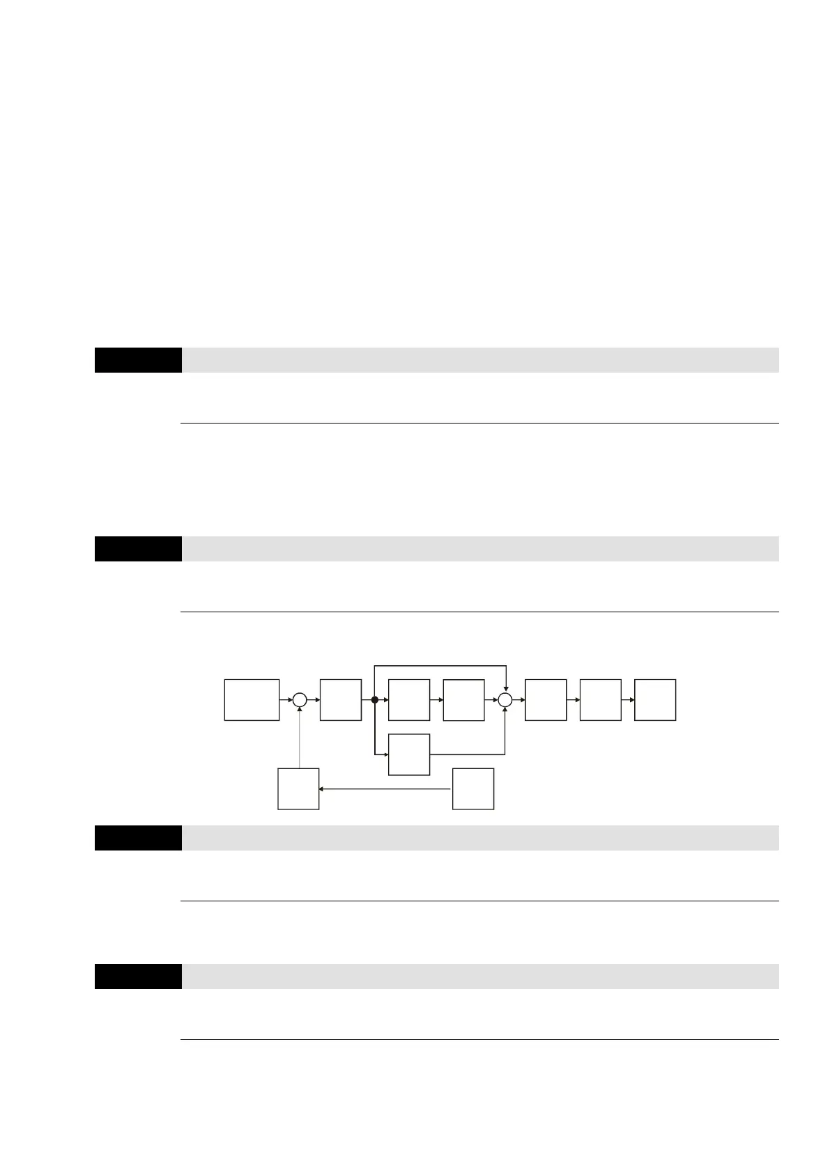
PID Control:
P
10.02
I
10.03
D
10.04
10.05
10.10
10.07
10.06
10.01
+
-
+
+
+
Setpoint
Input Freq.
Gain
PID
feedback
Integral
gain
limit
Output
Freq.
Limit
Digital
filter
Freq.
Command
PID Output Frequency Limit
Defines the percentage of the output frequency limit during the PID control. The formula is
Output Frequency Limit = Maximum Operation Frequency (Pr.01.00 × Pr.10.07%).
PID Feedback Signal Error Deviation Detection Time
Defines the detection time when the PID feedback ACI signal is abnormal. You can also use it
when the system feedback signal response is extremely slow. (Setting the detection time to 0.0
disables the detection function.)
 Loading...


