Chapter 4 Parameters|VFD-EL-W
94
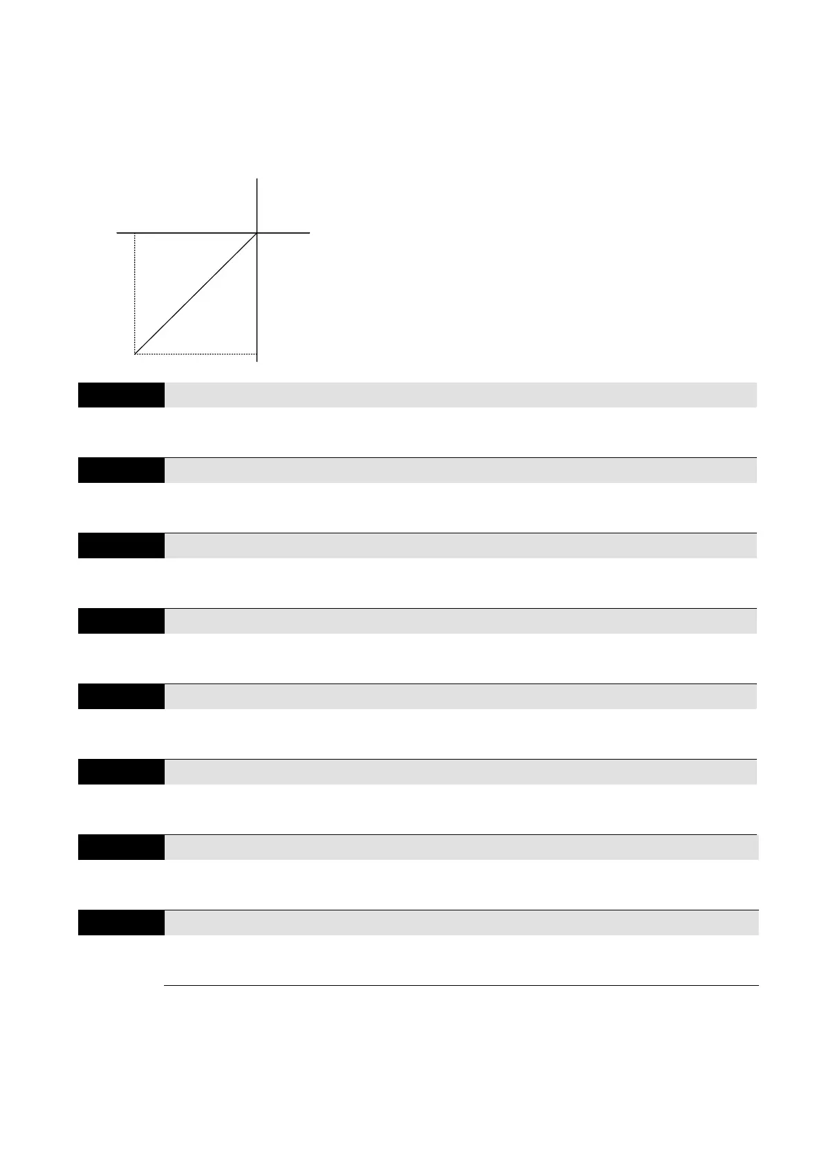
Example 8:
This example uses negative slope.
The rotate direction of this application cannot be changed, and the drive can only operates in a
reverse direction. Pay extra attention when using this application.
0Hz
REV
Min.(0V)
Max.(5V)
60Hz
FWD
Frequency/Hz
Potentiometer
(voltage/V)
Default:
Pr.01.00=60 Hz Max. operation frequency
Pr.04.00=100 % Bias adjustment
Pr.04.01=1 Bias direction adjustment
Pr.04.02=100 % Gain of frequency adjustment
Pr.04.03=1 No negative bias command
Minimum AVI Input Voltage
Minimum AVI Input Frequency
0.0–100.0% [100% corresponds to Fmax (Pr.01.00)]
Maximum AVI Input Voltage
Maximum AVI Input Frequency
0.0–100.0% [100% corresponds to Fmax (Pr.01.00)]
Minimum ACI Input Current
Minimum ACI Input Frequency
0.0–100.0% [100% corresponds to Fmax (Pr.01.00)]
Maximum ACI Input Current
Maximum ACI Input Frequency
0.0–100.0% [100% corresponds to Fmax (Pr.01.00)]
Sets the corresponding function between analog input value and maximum operating frequency
(Pr.01.00) (used in open-loop control), as shown in the figure below.
 Loading...


