Chapter 4 Parameters|VFD-EL-W
93
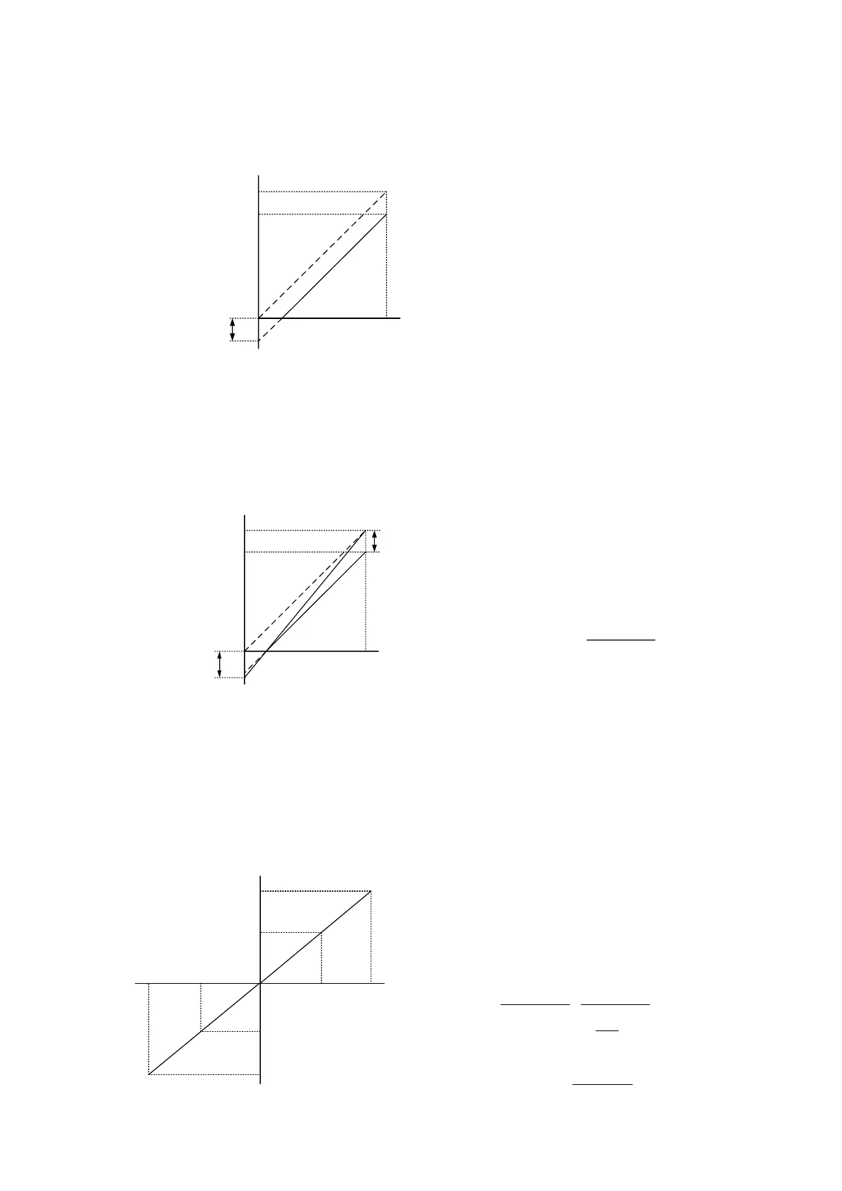
Example 5:
Using negative bias to set the frequency greatly reduces the noise interference. In a noisy
environment, do NOT use signals less than 1V to set the drive’s operation frequency.
Example 6:
This example is an extension application of Example 5. In addition, it uses the gain correction to
set to the maximum operating frequency. This type of application is extremely extensive, you can
apply it flexibly.
60Hz
0Hz
48Hz
Frequency
bias 15Hz
1V
Bias
adjustment
Max.(5V)
Min.
(0V)
Bias
Pr.01.00
Max.
operation
frequency
Frequency/Hz
Potentiometer
(voltage/V)
Default:
Pr.01.00=60 Hz Max. operation frequency
Pr.04.00=20.0 % Bias adjustment
Pr.04.01=1 Bias direction adjustment
Pr.04.02=125 % Gain of frequency adjustment
Pr.04.03=0 No negative bias command
To count the gain value
Pr.04.02
=
5V
(5-1)V
×100 %=125 %
Example 7:
This example is the culmination of all potentiometer applications. With the application of forward
and reverse rotation areas, it can be easily combined with the system to make various complex
applications. When this application is set, the forward and reverse commands of the external
terminals will automatically fail, pay extra attention.
60Hz
0Hz
2.5V
30Hz
60Hz
30Hz
Max.(5V)
Min.(0V)
To count the gain value
Pr.04.02
=
5V
[5-(2.5)]V
×100%=200%
To count the bias (See α in the formula)
60-(-60)Hz
5V
=
60-0Hz
α V
→
α=2.5V
Pr.04.00
=
2.5V
5V
×100%=50%
∴
Pr.01.00
Max.
operation
frequency
Frequency/Hz
REV
FWD
Potentiometer
(voltage/V)
Default:
Pr.01.00=60 Hz Max. operation frequency
Pr.04.00=50.0 % Bias adjustment
Pr.04.01=1 Bias direction adjustment
Pr.04.02=200 % Gain of frequency adjustment
Pr.04.03=1 No negative bias command
60Hz
0Hz
48Hz
1V
Max.(5V)
Min.
(0V)
Frequency/Hz
Pr.01.00
Max.
operation
frequency
Bias
Frequency
bias 12Hz
Potentiometer
(voltage/V)
Default:
Pr.01.00=60 Hz Max. operation frequency
Pr.04.00=20.0 % Bias adjustment
Pr.04.01=1 Bias direction adjustment
Pr.04.02=100 % Gain of frequency adjustment
Pr.04.03=0 No negative bias command
 Loading...


