Erect, assemble and connect F800
20 PR-2013-0105-GB • Subject to modifications • R2-04/2016
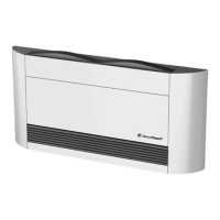
Prepare the unit as follows:
• Open or cut the outside air connection. Be sure
to hold the cut-out material tightly to avoid it fall-
ing back into the interior of the unit! Otherwise
the unit must be opened in order to remove the
cut-out material.
For units with rear wall mounting, the outside air
connection is mounted in front of the unit (see
“Set up in ancillary rooms (rear wall assembly)”
on page 20.
Fig. 4-14
• Screw on the outside-air connectors (accesso-
ry) with 2 screws.
• Connect air connection.
The installed thermostatic valve regulates the hot
water flow rate.
The heater supply is directly connected at the
valve (R 1/2"i) and the heater return line at the
heating register connection (R 1/2"i) (left unit side).
Fig. 4-15: Mixed-air operation
1: Outside-air connection
2: Heater water connection (supply) R1/2" (accessory)
3: Heater water connection (return line) R1/2" (accessory)
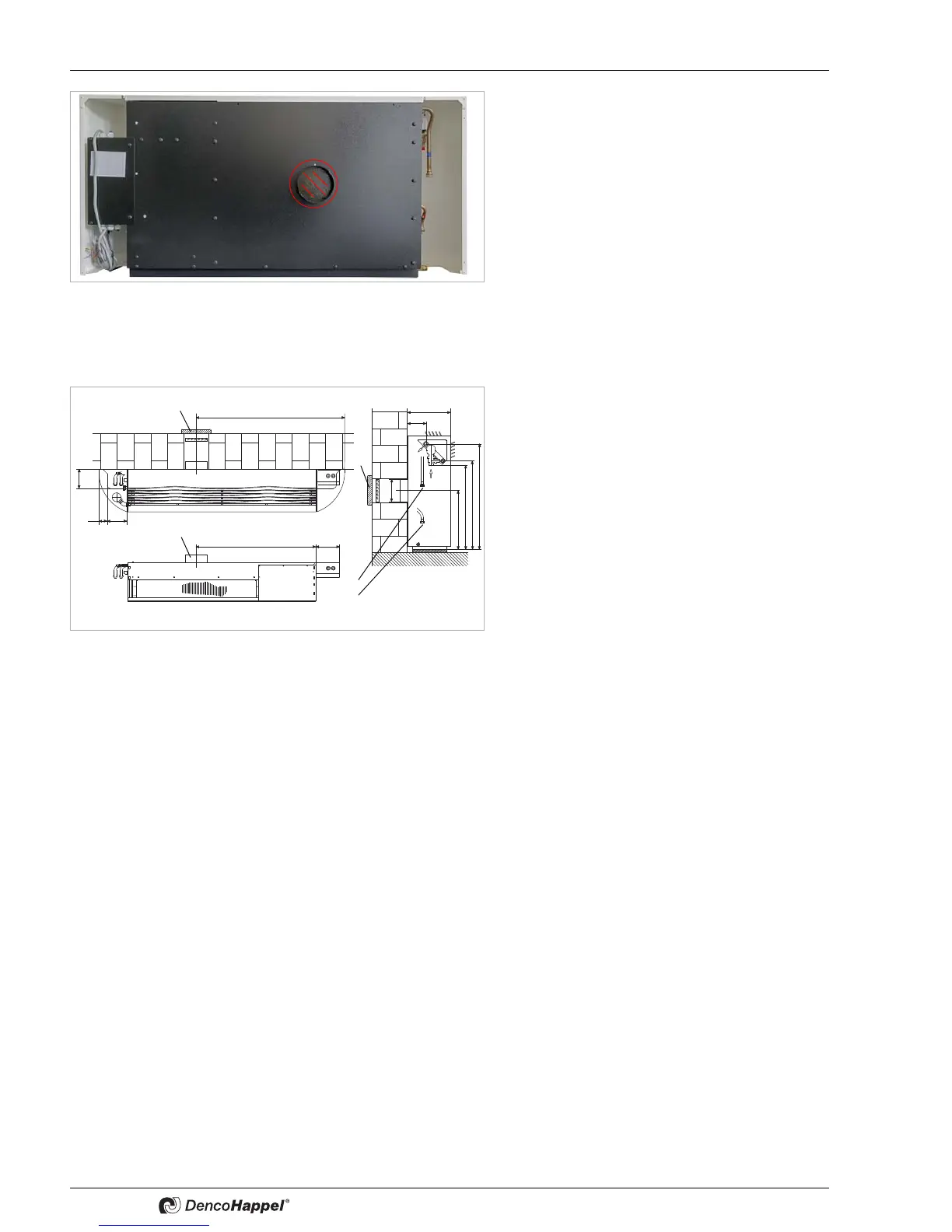
4.1.4 Set up in ancillary rooms (rear wall assembly)
Units to be installed in ancillary are delivered without casing.
The ambient temperature must be at least 20° C to avoid temperature shortfalls in the
unit and air ducts.
Rear-wall units must be set up in such a way, that the unit can be connected with short
duct pieces. The maximum total static pressure is 20 Pa. The pre-assembled flexible
connection for the supply air connection can be delivered as an accessory (see
“Adapter for extract-air connection for setting up in ancillary rooms” on page 21).
The unit is equipped with an adapter for connection to on-site exhaust air lines (e.g.
flexible air hoses). This is mounted before the air intake at the lower part of the unit
(see “Adapter for extract-air connection for setting up in ancillary rooms” on page 21).
Connectors with a diameter of 180 mm are provided for the connection of the hoses.