F800 Erect, assemble and connect
PR-2013-0105-GB • Subject to modifications • R2-04/2016 27
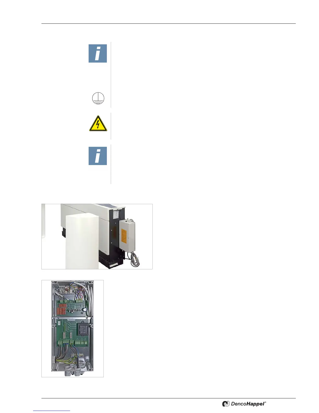
4.3 Electrical installation
• For the entire electrical installation, observe the VDE - directive 0100, part 702.
The electric connections are found below the right rounded lat-
eral casing (1).
• Unscrew the plastic screw on the lower panel as described
in the Fig. 4-3 on page 16.
• To install these lateral parts, pull them forwards.
Fig. 4-33
The operating voltage of the unit is 1Ph-230 V 50 Hz, the control voltage is 24 V pro-
tective extra-low voltage.
• Secure the unit separately with 16 A slow-blow circuit breakers and with earth
leakage circuit breakers according to the local regulations of the electric utility
company.
• Open switch box and connect according to circuit diagrams.
• Connect potential equalization.
Fig. 4-34
The electrical connection may only be performed by a qualified licensed electrician.
They must have proper professional training and experience in the relevant accident
prevention regulations, as well as other generally recognized safety and occupa-
tional health codes, perform unit jobs.
Ensure and observe protective measures!
When installing and connecting the unit, observe all protective measures for low-volt-
age systems according to the EU Directive as well as regulations and codes of the
local utility provider.
Ensure potential equalization and the earthing of the unit with all connected compo-
nents.
DANGER OF ELECTRICAL CURRENT!
Disconnect all electric power and ensure the power cannot be inadvertently ener-
gized; earth, short-circuit and block off all neighbouring live parts. Non-compliance
can lead to death or serious injury.
NOTICE!
The wiring must be carried out according to the attached equipment-specific electri-
cal switching and connection plans (see “Electrical connection” on page 28 ) and
national valid standards and guidelines.
Only separate mains power cable may be used.
• Never connect other units to this mains power cable.
 Loading...