Technical Description F800
10 PR-2013-0105-GB • Subject to modifications • R2-04/2016
Outside air
connection fittings
F8ZAA
– Diameter 150 mm
– For the operation of the basic unit with share fraction of fresh air
– Use only with extract fan (F8ZAV) and additional PWW heating register
Painted refrigeration pipe-
work
F8ZKL
– Improved corrosion protection with painted refrigeration circuit
Special paint finish
casing (RAL colors)
F8ZSL
Spare filter set F8ZEF
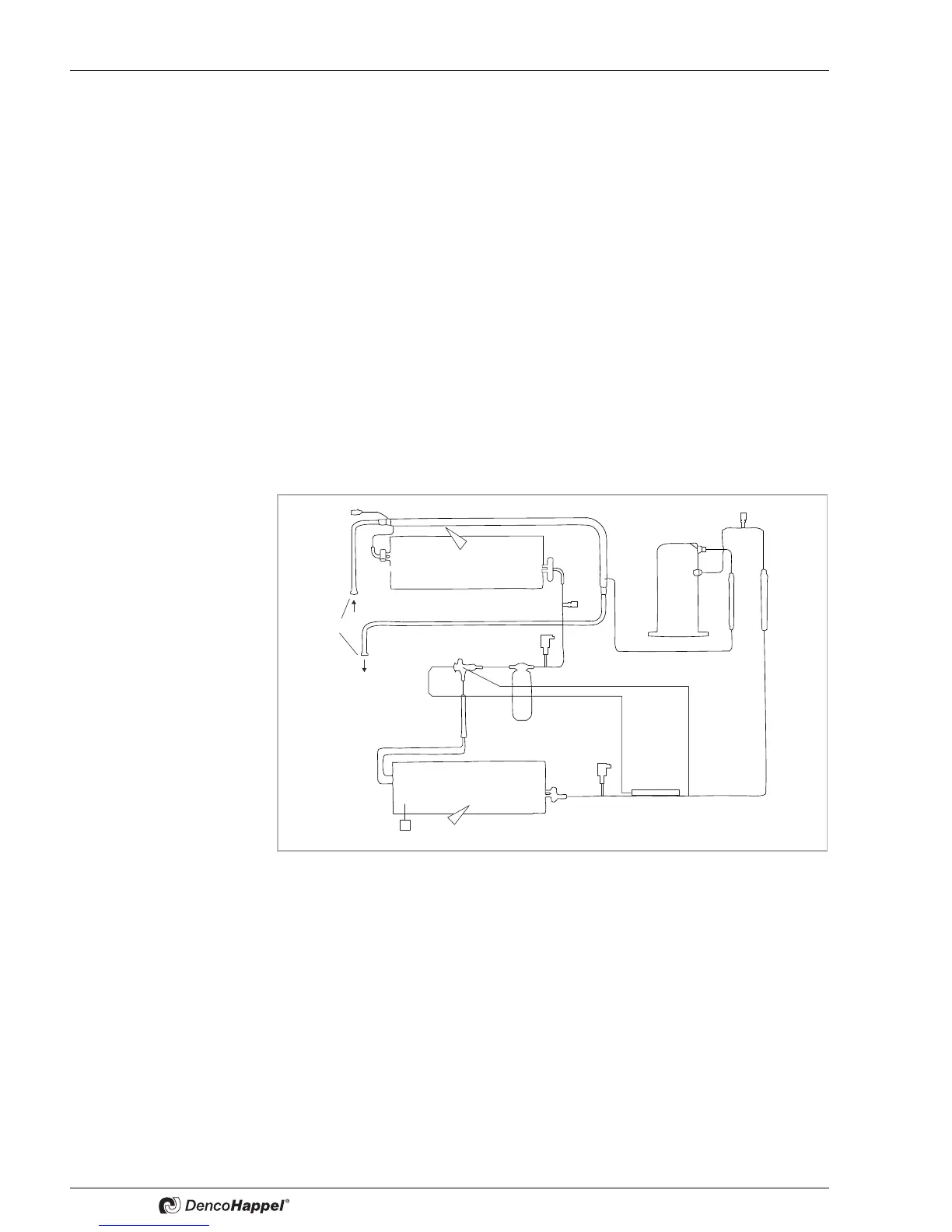
2.4 Functional principle of the F800
The figure shows the refrigeration circuit with pool water condenser essentially consist-
ing of: scroll compressor (1), air-cooled condenser (4) and pool water condenser
(Option)(3), expansion valve (8) and evaporator or air- cooler (9). Refrigeration circuit
filled with refrigerant.
1: compressor
3: pool water
condenser (accessory)
4: air-cooled condenser
5: high-pressure monitor
6: schrader valve
7: dryer/collector
8: expansion valve
9: evaporator (air cooler)
10: anti-icing
protection
thermostat
11: low-pressure limiter
12: venting valve
13 pool water
connection R 1/2"
Fig. 2-2: Refrigeration circuit
The hall air is evacuated by the centrifugal fan and cooled over the air cooler.
Depending on the humidity, the temperature can drop below the dew point; the water
steam in the hall air condenses on the fins of the air cooler and collects in the conden-
sate tray. The water condensate drained off through a pipe.
The dehumidified and cooled air is then re-warmed and supplied to the indoor swim-
ming pool hall.
 Loading...