EasyManua.ls Logo

Denon AVR-1913 Service Manual

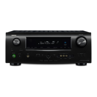
Denon AVR-1913
222 pages
To Next Page IconTo Next Page
Page #1 background imageLoading...
Page #1 background image
D&M Holdings Inc.
SERVICE MANUAL
e
e
Copyright 2014 D&M Holdings Inc. All rights reserved.
WARNING: Violators will be prosecuted to the maximum extent possible.
MODEL JP E3 E2 EK EA E1 E1K E1C
AVR-1913
P
AVR-2113CI
s
P
AVR-2113
P
d
P
INTEGRATED NETWORK AV RECEIVER
Ver. 8
S0892-1V08DM/DG1408
Some illustrations using in this service manual are slightly different from the actual set.
Please use this service manual with referring to the operating instructions without fail.
• For purposes of improvement, specications and design are subject to change without notice.
Please refer to the
MODIFICATION NOTICE.
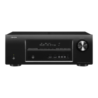
Table of Contents

Other manuals for Denon AVR-1913

Questions and Answers:

Denon AVR-1913 Specifications

General IconGeneral
Receiver type-
Audio output channels7.1 channels
Power output per channel (1KHz@6 Ohm)125 W
Power output per channel (20-20KHz@8 Ohm)90 W
HDMI in6
Audio (L/R) in5
Composite video in3
Component video (YPbPr/YCbCr) in1
Audio formats supportedAAC, FLAC, MP3, WMA
Ethernet LANYes
FM band range87.5 - 107.9 MHz
Supported radio bandsFM
Internet radio services supportedPandora, SIRIUS Internet Radio, Spotify, vTuner
Card reader integratedNo
Supported video modes1080p
Supported graphics resolutions1920 x 1080 (HD 1080)
Product colorBlack
Audio decodersDolby Digital Plus, Dolby Pro Logic IIz, Dolby TrueHD, DTS 96/24, DTS Neo:6, DTS-ES (Discrete 6.1), DTS-HD, DTS-HD Master Audio
Volume controlRotary
Weight and Dimensions IconWeight and Dimensions
Depth162 mm
Width434.3 mm
Height328.9 mm
Weight9099 g

Summary

About This Manual

What You Can Do With This Manual

Explains the functionalities available within the service manual.

Search for a Ref. No. (phrase)

Instructions on using the Acrobat Reader search function for reference numbers.

Using Adobe Reader (Windows Version)

Add Notes to This Data (Sign)

Describes how to use the Sign function to add notes to the manual.

Magnify Schematic / Printed Wiring Board Diagrams - 1

Instructions for magnifying parts of diagrams using keyboard and mouse.

Print a Magnified Part of the Manual

Details on configuring printer settings for printing magnified manual sections.

Magnify Schematic / Printed Wiring Board Diagrams - 2

Magnify Schematic / Printed Wiring Board Diagrams - 3

Explains how to use the Loupe Tool function for magnifying diagrams.

Safety Precautions

Leakage Current Check

Outlines the procedure and limits for performing a leakage current check.

Cautions Concerning Electric Shock

General cautions for servicing and inspection, including electric shock.

Cautions Concerning Important Safety Parts

Highlights the importance of using designated safety parts and their identification.

Note for Schematic Diagram

Note for Parts List

Provides notes on parts list conventions, including "nsp" and "*" marked parts.

Technical Specifications

Audio Section

Details the technical specifications for the audio amplifier section.

Video Section

Details the technical specifications for the video section.

Tuner Section

Details the technical specifications for the tuner section.

General

Provides general specifications like power supply, consumption, and dimensions.

Remote Control Unit (RC-1167)

Details the specifications for the remote control unit.

Cautions in Servicing

Initializing Integrated Network AV Receiver

Explains the initialization procedure for the integrated network AV receiver.

Service Jig

Describes the JIG kits used for servicing and firmware updates.

Disassembly

1. Front Panel Assy

Details the disassembly procedure for the front panel assembly.

2. PCB MX Port/PCB RS232C (AVR-2113CIE3 only)

Describes the disassembly of the MX PORT/RS232C PCB.

3. PCB HDMI

Details the disassembly procedure for the PCB HDMI.

4. Power Trans Main

Outlines the disassembly of the main power transformer.

5. PCB Video Assy

Details the disassembly procedure for the PCB VIDEO ASSY.

6. PCB SMPS

Details the disassembly procedure for the PCB SMPS.

7. Radiator Assy

Details the disassembly procedure for the radiator assembly.

Special Mode

Special Mode Setting Button (for 1913E3 model)

Explains how to access special modes using buttons on the 1913E3 model.

Special Mode Setting Button (for 2113CIE3/2113E2/E1C model)

1. µcom/DSP Version Display Mode

1.1. Operation Specifications

Explains how to display the µcom/DSP version information.

1.2. Display Order

Details the order in which error information and versions are displayed.

1.3. Error Display

Condition

Explains the conditions that trigger specific error displays.

Status

Details the status messages displayed for each error condition.

FL Display

Shows the display output for each error condition.

Trouble Shooting

Provides troubleshooting steps for each identified error.

1.4. Version Display on the Setup Menu

GUI Image

Illustrates the firmware version display on the GUI.

2. Panel/Remote Lock Selection Mode

2.1. Behavior Specifications

Describes the behavior and purpose of the panel/remote lock modes.

2.2. Starting Up

Instructions on how to start up the panel/remote lock selection mode.

2.3. Mode Selection Method and How Each Mode Is Displayed

Explains how to select modes and how they are displayed on the FL display.

3. Service Related Selection Mode

3.1. Behavior Specifications

Describes the behavior and purpose of Diagnostic, Protection, and 232C Clear modes.

3.2. Starting Up

Instructions on how to start up the service related selection modes.

3.3. Canceling Diagnostic Mode

Explains how to cancel the diagnostic mode.

3.4. Diagnostic Mode (Video/Audio (Signal) Path Confirmation Mode)

3.4.1. Operation

Details the operation steps for confirming video/audio signal paths.

3.4.2. Video System Confirmation Items

Lists the video system confirmation items and their operating procedures.

3.4.3. Audio System Confirmation Items

Confirmation Item

Lists the audio system confirmation items and their settings.

3.5. Errors Checking Mode (Displaying the Protection History)

3.5.1. Operation Specifications

Explains the operation specifications for the error checking mode.

3.5.2. About the Display on the FL Display

Describes the information displayed on the FL display for various error codes.

3.5.3. Clearing the Protection History

Warning Indication by the POWER LED

Explains the POWER LED indications for different protection incidents.

3.6. 232C Standby Clear Mode

Details the operation for clearing the 232C standby mode.

4. Remote ID Setup Mode

4.1. Specifications

Explains the purpose and specifications of the Remote ID Setup mode.

4.2. Setting the AV Receivers

Provides instructions on setting the AV receiver's remote ID.

5. Network Initialization Mode

5.1. Behavior Specifications

Describes the behavior and purpose of the NETWORK Initialization mode.

5.2. Starting Up

Block Diagram

fig.1

Displays the video block diagram for the unit.

Video Block Diagram

fig.2

Shows the video block diagram, similar to fig. 1.

Video Block Diagram

fig.3

Displays the video block diagram, similar to fig. 1 and 2.

Video Block Diagram

fig.4

Displays the video block diagram, similar to fig. 1, 2, and 3.

Audio Block Diagram

fig.5

Illustrates the audio block diagram of the unit.

Audio Block Diagram

fig.6

Shows the audio block diagram, similar to fig. 5.

Audio Block Diagram

fig.7

Displays the audio block diagram, similar to fig. 5 and 6.

Audio Block Diagram

fig.8

Shows the audio block diagram, similar to fig. 5, 6, and 7.

Audio Block Diagram

fig.9

Displays the audio block diagram, similar to fig. 5, 6, 7, and 8.

Audio Block Diagram

fig.10

Shows the audio block diagram, similar to previous figures.

Audio Block Diagram

fig.11

Displays the audio block diagram, similar to previous figures.

Audio Block Diagram

fig.12

Shows the audio block diagram, similar to previous figures.

VCC Block Diagram

Jig for Servicing

Connection of PCB HDMI Jig

Details the preparation and procedures for connecting the PCB HDMI JIG.

When the Microprocessor Is Replaced With a New One

Procedure for Upgrading the Version of the Firmware

Outlines the procedure for upgrading firmware using DFW.

1. How to Update by DFW

1.1. Preparations Before Starting the Operation

Lists the necessary preparations for updating firmware using DFW.

1.2. Connection of AV Receiver

Details the connection steps for the AV receiver and PC for firmware update.

1.3. Turn On the AV Receiver

Explains how to power on the AV receiver for firmware update.

1.4. Run the DFW

Instructions on running the DFW software for firmware update.

1.5. Communication Check

Details how to check the communication between PC and AV receiver.

1.6. Download the Firmware

(1) Click the "Load" Button

Describes clicking the "Load" button to initiate firmware download.

(2) Download the Firmware from the Specified Download Source to PC

Instructions for downloading firmware from the specified source to PC.

1.7. Complete the Firmware Updating

1.8. Notice:

Provides important notices and precautions for firmware updates.

2. How to Update by DPMS

2.1. Connecting to the Network

Explains the system requirements and settings for network connection for firmware updates.

2.2. Checking and Updating the Firmware

Details how to check for and perform firmware updates via DPMS.

2.3. About the Error Code

Details of Error Code

Lists error codes, their details, and coping strategies during DPMS firmware updates.

3.4. Device Display During Firmware Update

Confirming the Firmware's Number After Upgraded

Instructions on how to confirm the firmware version after an update.

3. How to Update by USB Memory

3.1. Connecting to the Network

Lists system requirements for connecting to the network via USB Memory.

3.2. Download the Firmware

Details the procedure for downloading firmware using USB memory.

3.3. About the Error Code

Details of Error Code

Lists error codes, details, and coping strategies for USB memory firmware updates.

3.4. Device Display During Firmware Update

Confirming the Firmware's Number After Upgraded

Instructions on how to confirm the firmware version after a USB update.

Adjustment

Audio Section

Details the audio section adjustment procedures, specifically for idling current.

Surround Modes and Parameters

Sound Modes and Surround Parameters

Explains the available sound modes and adjustable surround parameters.

Sound Mode

Surround Parameter

Lists surround parameters and their adjustability across different sound modes.

n Types of Input Signals, and Corresponding Sound Modes

Sound Mode

Shows input signal types and the corresponding selectable sound modes.

Trouble Shooting

1. Power

Provides troubleshooting steps for power-related issues, including no power.

1.2. Fuse Is Blown

Details troubleshooting steps when a fuse is blown.

2. Analog Video

A

Is the power supply voltage correctly output?

Checks power supply voltage at specific points for troubleshooting.

Check on set value of each IC.

Details checking IC voltage values for troubleshooting.

Is the signal output from the video amplifier?

Guides on checking the signal output from the video amplifier.

Is the signal input to selector IC5001?

Guides on checking the signal input to the selector IC.

B

Check the input signal to VIDEO DECODER.

Guides on checking the input signal to the VIDEO DECODER.

C

Is the power supply voltage correctly output?

Checks power supply voltage at specific points for troubleshooting.

Check on set value of each IC.

Details checking IC voltage values for troubleshooting.

Is the signal output from the video amplifier?

Guides on checking the signal output from the video amplifier.

Is the signal input to video amplifier?

Guides on checking the signal input to the video amplifier.

HDMI Test Point (AVR-1913E3)

Detail A

Shows detailed view of HDMI test points, including connector pins.

Detail B

Shows detailed view of HDMI test points, including resistor labels.

HDMI Test Point and Waveforms (AVR-2113CIE3 / E2 / E1C)

Detail A

Shows detailed view of HDMI test points for specific models.

Detail B

Shows detailed view of HDMI test points for specific models.

3. HDMI/DVI

3.1. No Picture or Sound Is Output (HDMI to HDMI)

Troubleshooting guide for HDMI output issues (no picture or sound).

Check BD/DVD Player.

Guides on checking the BD/DVD player for HDMI output issues.

Check TV

Is the TV HDCP-compatible?

Checks for TV HDCP compatibility as a troubleshooting step.

Is the TV Compatible with Resolutions of 1080P?

Checks for TV resolution compatibility as a troubleshooting step.

Is the Set's Input Set to HDMI?

Guides on checking the set's input settings for HDMI.

Are the Picture and Sound Output when a Different TV Is Used?

Checks if the issue persists with a different TV.

The Set Does Not Recognize the TV.

Explains checks related to the set not recognizing the TV.

The BD/DVD Player Does Not Recognize the Connection With the Set.

Addresses issues where the BD/DVD player fails to connect with the set.

Video Convert : Is the picture output when it is set to off?

Checks the impact of the VIDEO CONVERT setting on picture output.

Check Operation of U1(ADV3002).

Check Power Supply.

Guides on checking power supply to specific ICs.

Check RESET.

Guides on checking RESET waveforms for specific ICs.

Check Control Signal (I2C).

Guides on checking the I2C control signal waveform.

Check Output Signal.

Guides on checking TMDS and DDC waveforms.

Check Operation of U1601(ADV8002 (AVR-1913) / ADV8003 (AVR-2113))

Check Power Supply.

Guides on checking power supply to U1601.

Check Xtal Oscillator.

Guides on checking the xtal oscillator for U1601.

Check RESET.

Guides on checking the RESET waveform for U1601.

3.2. HDMI Test Point and Waveforms (AVR-1913E3)

Detail A

Shows detailed view of HDMI test points and waveforms for AVR-1913E3.

Detail B

Shows detailed view of HDMI test points and waveforms for AVR-1913E3.

HDMI Test Point and Waveforms (AVR-2113CIE3 / E2 / E1C)

Detail A

Shows detailed view of HDMI test points and waveforms for specific models.

Detail B

Shows detailed view of HDMI test points and waveforms for specific models.

HDMI Test Point and Waveforms (AVR-2113CIE3 / E2 / E1C)

Detail A

Shows detailed view of HDMI test points and waveforms for specific models.

Detail B

Shows detailed view of HDMI test points and waveforms for specific models.

HDMI Test Point and Waveforms (AVR-2113CIE3 / E2 / E1C)

Detail C

Shows detailed view of HDMI test points for specific models.

Detail D

Shows detailed view of HDMI test points for specific models.

Detail E

Shows detailed view of HDMI test points for specific models.

Detail F

Shows detailed view of HDMI test points for specific models.

DDC_CLK/DDC_DATA/TMDS : Check Items HDMI to HDMI (17)/(19)/(24)

Timing Waveform Illustration from the Start of CEC3.3V to When Reset Is Released : Check Items (22)

Controlled Waveform (I2C), When Power Is Turned On : Check Items (23)

Timing Waveform Illustration from the Start of CEC3.3V to When Reset Is Released : Check Items (30)

Timing Waveform Illustration from the Start of CEC3.3V to When Reset Is Released : Check Items (27)

4. Audio

4.1. Audio Check

Guides through checking audio output for different input sources.

4.2. Power Amp (AMP UNIT)

No Sound Is Output.

Troubleshooting steps for no sound output from the power amplifier.

Is the Power Transistor Open or Short Circuited?

Checks power transistor status for no sound issues.

Is the Emitter Resistance of the Power Transistor Open?

Checks emitter resistance of the power transistor.

Is the Base Resistance of the Power Transistor Open?

Checks base resistance of the power transistor.

Is Other Transistor Trouble?

Guides on checking for other transistor issues.

Is Other Resistance Trouble?

Guides on checking for other resistance issues.

4.3. Analog Audio

No Sound Is Output

Troubleshooting steps for no sound output from analog audio circuits.

Is the Voltage of ±7V Supplied to INPUT B'D CN4004?

Checks power supply voltage to INPUT B'D CN4004.

Is the Audio Signal Transmitted to INPUT B'D CN401?

Checks audio signal transmission to INPUT B'D CN401.

Is the Serial Data for Electronic Volume Transmitted to INPUT B'D CP4200?

Checks serial data transmission for electronic volume.

5. Network/USB

5.1. Cannot Connect to Network

Troubleshooting guide for network connectivity issues.

Checking the Environment

Steps to check the network environment for connectivity issues.

Checking the Settings

Guides on checking network and router settings for connectivity.

Checking the Set (AVR-1913/2113)

Details checks on the set itself for network connectivity issues.

5.2. USB Device Is Not Recognized

Checking the USB Device

Guides on checking USB device compatibility and hub usage.

Checking the Set (AVR-1913/2113)

Details checks on the set for USB device recognition issues.

5.3. No Picture or No Sound Is Output

Checking the Set (AVR-1913/2113):(If no picture is output)

Guides troubleshooting for no picture output.

Checking the Set (AVR-1913/2113):(If no sound is output)

Guides troubleshooting for no sound output.

HDMI Test Point (AVR-1913E3)

HDMI Test Point (AVR-2113CIE3 / E2 / E1C)

Shows HDMI test points for specific models.

USB Test Point

Shows USB test points for connection.

6. SMPS

DC 5V is Not Output.

Troubleshooting steps for DC 5V output failure from the SMPS.

Operation Waveform for Each Part

SMPS Unit (Unloaded)

Shows operation waveforms for the SMPS unit when unloaded.

Set

Shows operation waveforms for the set.

Audio Check PATH

CHECK1

Checks analog audio block path.

CHECK2

Checks digital audio block path.

CHECK3

Checks ADC block path.

CHECK4

Checks HDMI block path.

CHECK5

Checks HDMI audio path.

CHECK6

Checks digital audio block and HDMI block connectivity.

Clock Flow & Wave Form in Digital Block

WAVE FORM

Shows waveforms for DIR input, output, and DAC input.

Test Point (AVR-1913E3)

Illustrates test points on the HDMI board for AVR-1913E3.

Detail A

Detailed view of test points and signals C1(RX0).

Detail B

Detailed view of test points and signals LRCK, BICK, DATA_F, DATADIR1, FSDIR1, 64FSDIR1.

Test Point (AVR-2113CIE3 / E2 / E1C)

Detail A

Shows detailed view of HDMI test points for specific models.

Detail B

Shows detailed view of HDMI test points for specific models.

Level Diagram

FRONT ch

Illustrates the level diagram for the front channel.

Level Diagram

CENTER ch

Illustrates the level diagram for the center channel.

Level Diagram

SUBWOOFER ch

Illustrates the level diagram for the subwoofer channel.

Level Diagram

SURROUND ch

Illustrates the level diagram for the surround channel.

Level Diagram

SURR.BACK ch

Illustrates the level diagram for the surround back channel.

Printed Wiring Boards

HDMI (AVR-1913E3) (Component Side)

Shows the printed wiring board for the HDMI section (component side).

HDMI (AVR-1913E3) (Foil Side)

HDMI (AVR-2113CIE3 / E2 / E1C) (Component Side)

HDMI (AVR-2113CIE3 / E2 / E1C) (Foil Side)

Printed Wiring Boards

FRONT HDMI (Component Side)

Shows the printed wiring board for the front HDMI section (component side).

FRONT HDMI (Foil Side)

Shows the printed wiring board for the front HDMI section (foil side).

Optional Circuit (Component Side)

Shows the printed wiring board for the optional circuit (component side).

Optional Circuit (Foil Side)

Shows the printed wiring board for the optional circuit (foil side).

RS232 (Component Side)

Shows the printed wiring board for the RS232 interface (component side).

RS232 (Foil Side)

Shows the printed wiring board for the RS232 interface (foil side).

FRONT (Component Side)

FRONT (Foil Side)

FUNCTION

F/H_GUIDE

Explains the function of the F/H_GUIDE.

CNT

Explains the function of the CNT.

USB

GUIDE L

Shows the printed wiring board for GUIDE L.

GUIDE R

Shows the printed wiring board for GUIDE R.

TOP_GUIDE

Shows the printed wiring board for the TOP_GUIDE.

7CH AMP

7CH AMP (Component Side)

Shows the printed wiring board for the 7CH AMP (component side).

7CH AMP (Foil Side)

Shows the printed wiring board for the 7CH AMP (foil side).

VIDEO

VIDEO (Component Side)

Shows the printed wiring board for the VIDEO section (component side).

VIDEO (Foil Side)

Shows the printed wiring board for the VIDEO section (foil side).

FRONT CNT

FRONT CNT (Component Side)

Shows the printed wiring board for the FRONT CNT (component side).

FRONT CNT (Foil Side)

Shows the printed wiring board for the FRONT CNT (foil side).

INPUT

INPUT (Component Side)

Shows the printed wiring board for the INPUT section (component side).

INPUT (Foil Side)

Shows the printed wiring board for the INPUT section (foil side).

MAIN

MAIN (Component Side)

Shows the printed wiring board for the MAIN section (component side).

MAIN (Foil Side)

Shows the printed wiring board for the MAIN section (foil side).

SMPS

SMPS (Component Side)

Shows the printed wiring board for the SMPS section (component side).

SMPS (Foil Side)

Shows the printed wiring board for the SMPS section (foil side).

SCHEMATIC DIAGRAMS (1/26)

HDMI SW UNIT

Provides the schematic diagram for the HDMI SW unit.

SCHEMATIC DIAGRAMS (2/26)

FRONT HDMI UNIT

Provides the schematic diagram for the FRONT HDMI unit.

SCHEMATIC DIAGRAMS (3/26)

HDMI RX UNIT

Provides the schematic diagram for the HDMI RX unit.

SCHEMATIC DIAGRAMS (4/26)

HDMI TX UNIT

Provides the schematic diagram for the HDMI TX unit.

SCHEMATIC DIAGRAMS (5/26)

HDMI TX DDR UNIT

Provides the schematic diagram for the HDMI TX DDR unit.

SCHEMATIC DIAGRAMS (6/26)

DSP UNIT

Provides the schematic diagram for the DSP unit.

SCHEMATIC DIAGRAMS (7/26)

DIR/PLD UNIT

Provides the schematic diagram for the DIR/PLD unit.

SCHEMATIC DIAGRAMS (8/26)

MAIN DAC UNIT

Provides the schematic diagram for the MAIN DAC unit.

SCHEMATIC DIAGRAMS (9/26)

DM860A UNIT

Provides the schematic diagram for the DM860A unit.

SCHEMATIC DIAGRAMS (10/26)

NET PHY UNIT

Provides the schematic diagram for the NET PHY unit.

SCHEMATIC DIAGRAMS (11/26)

CPU UNIT

Provides the schematic diagram for the CPU unit.

SCHEMATIC DIAGRAMS (12/26)

CPU LEVEL CHG UNIT

Provides the schematic diagram for the CPU LEVEL CHG unit.

SCHEMATIC DIAGRAMS (13/26)

DIGITAL CNT UNIT

Provides the schematic diagram for the DIGITAL CNT unit.

SCHEMATIC DIAGRAMS (14/26)

D. SUPPLY UNIT

Provides the schematic diagram for the D. SUPPLY unit.

SCHEMATIC DIAGRAMS (15/26)

7CH-AMP UNIT (1/2)

Provides the schematic diagram for the 7CH AMP unit (part 1).

SCHEMATIC DIAGRAMS (16/26)

7CH-AMP UNIT (2/2)

Provides the schematic diagram for the 7CH AMP unit (part 2).

SCHEMATIC DIAGRAMS (17/26)

SPK REG SMPS UNIT (1/4)

Provides the schematic diagram for the SPK REG SMPS unit (part 1).

SCHEMATIC DIAGRAMS (18/26)

SPK REG SMPS UNIT (2/4)

Provides the schematic diagram for the SPK REG SMPS unit (part 2).

SCHEMATIC DIAGRAMS (19/26)

SPK REG SMPS UNIT (3/4)

Provides the schematic diagram for the SPK REG SMPS unit (part 3).

SCHEMATIC DIAGRAMS (20/26)

SPK REG SMPS UNIT (4/4)

Provides the schematic diagram for the SPK REG SMPS unit (part 4).

SCHEMATIC DIAGRAMS (21/26)

INPUT UNIT

Provides the schematic diagram for the INPUT unit.

SCHEMATIC DIAGRAMS (22/26)

FRONT UNIT (1/2)

Provides the schematic diagram for the FRONT unit (part 1).

SCHEMATIC DIAGRAMS (23/26)

FRONT UNIT (2/2)

Provides the schematic diagram for the FRONT unit (part 2).

SCHEMATIC DIAGRAMS (24/26)

RS232 / OPTIONAL CIRCUIT UNIT

Provides the schematic diagram for the RS232/Optional Circuit unit.

SCHEMATIC DIAGRAMS (25/26)

VIDEO F/CNT UNIT (1/2)

Provides the schematic diagram for the VIDEO F/CNT unit (part 1).

SCHEMATIC DIAGRAMS (26/26)

VIDEO F/CNT UNIT (2/2)

Provides the schematic diagram for the VIDEO F/CNT unit (part 2).

Wiring Diagram

Exploded View

Parts List of Exploded View

Semiconductors Group

Lists semiconductor parts for the exploded view.

Parts Indicated by "nsp"

Notes that parts marked "nsp" are not supplied.

Parts Indicated by "★" Mark

Notes that parts marked "*" are not illustrated in the exploded view.

Parts Listed Below Are Only for Maintenance

Notes that listed parts are for maintenance and may differ in appearance.

Ref. No.

Part No.

Lists part numbers for various components like WINDOW, BADGE, LENS, PLATE, etc.

Part Name

Lists the names of various parts, such as WINDOW, BADGE, LENS, PLATE, etc.

Remarks

Provides remarks for parts, including model compatibility and other notes.

Screws

Lists various screw types with their specifications and part numbers.

Ref. No.

Part No.

Lists part numbers for various components like BRACKET, CABLE, FUSE, TRANS, etc.

Part Name

Lists the names of various parts, such as BRACKET, CABLE, FUSE, TRANS, etc.

Remarks

Provides remarks for parts, including model compatibility and other notes.

Packing View

Parts List of Packing & Accessories

Ref. No.

Lists reference numbers for packing and accessory parts.

Part No.

Lists part numbers for packing and accessory items like POLY BAG, ANTENNA, WIRE, etc.

Part Name

Lists the names of packing and accessory items such as POLY BAG, ANTENNA, WIRE, etc.

Remarks

Provides remarks for packing and accessory parts, including model destinations.

Semiconductors

1. IC's

Lists major semiconductor ICs with their functions and pin details.

R5F56108VNFP (HDMI : U3002)

Provides pin function details for the R5F56108VNFP IC.

R5F56108VNFP Terminal Functions

Details the function of each terminal pin for the R5F56108VNFP IC.

Pin Pin Name

Symbol

Lists symbols used for various pins and their functions.

I/O

Indicates the input/output direction for each pin.

LvCnv

Specifies the logic level conversion for pins.

STBY

Indicates pin behavior in standby mode.

STOP

Indicates pin behavior in stop mode.

CEC STBY

Indicates pin behavior in CEC standby mode.

Function

Describes the function of each pin.

ADV3002BSTZ (HDMI : U1001)

ADV3002BSTZ Block Diagram

Provides the block diagram for the ADV3002BSTZ IC.

ADV3002BSTZ Terminal Functions

Details the terminal functions for the ADV3002BSTZ IC.

AD8195ACPZ (HDMI : U1201)

AD8195ACPZ Block Diagram

Provides the block diagram for the AD8195ACPZ IC.

AD8195ACPZ Terminal Functions

Details the terminal functions for the AD8195ACPZ IC.

AD8195ACPZ Block Diagram

LC89058W-E (HDMI : U2203)

Pin Functions

Lists the pin functions for the LC89058W-E IC.

LC89058W-E Block Diagram

Continued from Preceding Page.

Continues the pin function descriptions for LC89058W-E.

Figure 3. Pin Configuration

Shows the pin configuration of the LC89058W-E IC.

Table 6. Pin Function Descriptions

Provides detailed pin function descriptions for the LC89058W-E IC.

ADSP21487KSWZ3B (HDMI : U2001)

ADSP21487KSWZ3B Terminal Function

Details the terminal functions for the ADSP21487KSWZ3B IC.

W9864G6JH-6 Pin Description

5. PIN DESCRIPTION

Lists the pin descriptions for the W9864G6JH-6 IC.

W9864G6JH-6 Pin Description

PIN NUMBER

Lists the pin numbers for the W9864G6JH-6 IC.

PIN NAME

Lists the pin names for the W9864G6JH-6 IC.

FUNCTION

Describes the function of each pin for the W9864G6JH-6 IC.

DESCRIPTION

Provides detailed descriptions for the W9864G6JH-6 IC pins.

W9864G6JH-6 Block Diagram

EN29LV160BB-70TIP (HDMI : U2003)

EN29LV160BB-70TIP Block Diagram

Provides the block diagram for the EN29LV160BB-70TIP IC.

Figure 2 : 48-TSOP1 / 63-FBGA Contact, x8 Device

Shows the pin configuration for TSOP1 and FBGA packages.

Table 1 : Signal Names

Lists the signal names for the EN29LV160BB-70TIP IC.

Table 2 : Pin Description

Provides pin descriptions for the EN29LV160BB-70TIP IC.

AK5358BET Pin Function

AK5358BET Pin Function

Pin No.

Lists the pin numbers for the AK4358VQ IC.

Pin Name

Lists the pin names for the AK4358VQ IC.

I/O

Indicates the input/output direction for each pin.

Function

Describes the function of each pin.

PCM5100 (HDMI:U2401)

PCM510x Block Diagram

Provides the block diagram for the PCM510x series ICs.

Table 2. Terminal Functions, PCM510x

Lists the terminal functions for the PCM510x series ICs.

Table 1. Differences Between PCM510x Devices

Details the differences between PCM510x devices.

H27U1G8F2BTR-BC (HDMI : U2603)

H27U1G8F2BTR-BC Pin Function

Lists the pin functions for the H27U1G8F2BTR-BC IC.

Figure 2 : 48-TSOP1 / 63-FBGA Contact, x8 Device

Shows the pin configuration for TSOP1 and FBGA packages.

Table 1 : Signal Names

Lists the signal names for the H27U1G8F2BTR-BC IC.

Table 2 : Pin Description

Provides pin descriptions for the H27U1G8F2BTR-BC IC.

H27U1G8F2BTR-BC Block Diagram

A3V56S30FTP-G6 Pin Function

Pin Descriptions

Details the pin descriptions for the A3V56S30FTP-G6.

A3V56S30FTP-G6 Pin Function

SYMBOL

Lists symbols used for various pins.

TYPE

Indicates the type of pin (Input, Output, I/O, Supply).

DESCRIPTION

Describes the function of each pin.

A3V56S30FTP-G6 Block Diagram

SAA7121H (HDMI : U2803)

SAA7121H Block Diagram

Provides the block diagram for the SAA7121H IC.

SAA7121H Pin Description

PIN No.

Lists the pin numbers for the SAA7121H IC.

Pin Name

Lists the pin names for the SAA7121H IC.

I/O

Indicates the input/output direction for each pin.

Function

Describes the function of each pin.

R2A15218FP (INPUT : IC4200)

LEVEL DIAGRAM

Illustrates the level diagram for the front channel.

LEVEL DIAGRAM

Illustrates the level diagram for the center channel.

LEVEL DIAGRAM

Illustrates the level diagram for the subwoofer channel.

LEVEL DIAGRAM

Illustrates the level diagram for the surround channel.

R2A15218FP Pin Function

PIN No.

Lists the pin numbers for the R2A15218FP IC.

Name

Lists the pin names for the R2A15218FP IC.

I/O

Indicates the input/output direction for each pin.

Function

Describes the function of each pin.

NJM2586AM (VIDEO : IC5002)

NJM2586AM (VIDEO : IC5002)

Shows the block diagram for the NJM2586AM IC.

2. FL DISPLAY

PIN CONNECTION

Shows the pin connection details for the FL display.

GRID ASSIGNMENT

ANODE CONNECTION

PARTS LIST OF PCB UNIT

SEMICONDUCTORS GROUP

Lists semiconductor components for the 7CH AMP PCB UNIT ASS'Y.

Parts Indicated by "nsp"

Notes that parts marked "nsp" are not supplied.

Parts Listed Below Are Only for Maintenance

Notes that listed parts are for maintenance and may differ in appearance.

Ref. No.

Part No.

Lists part numbers for various resistors, including R404, R406, R408, etc.

Part Name

Lists the names of various resistors, including R, FIXED, METAL FILM, etc.

Remarks

Provides remarks for resistors, including flame retardant and model compatibility.

Ref. No.

Part No.

Lists part numbers for various capacitors, including C4066, C4068, C4070, etc.

Part Name

Lists the names of various capacitors, including C, CERAMIC, FILM, etc.

Remarks

Provides remarks for capacitors, including model compatibility and type.

CAPACITORS GROUP

Lists capacitor components with their specifications.

Ref. No.

Part No.

Lists part numbers for various capacitors, including C4066, C4068, C4070, etc.

Part Name

Lists the names of various capacitors, including C, CERAMIC, FILM, etc.

Remarks

Provides remarks for capacitors, including model compatibility and type.

OTHERS PARTS GROUP

Lists other parts like BRACKET, CN, CP, JACK, etc.

Ref. No.

Part No.

Lists part numbers for various capacitors, including C476, C477, C479, etc.

Part Name

Lists the names of various capacitors, including C, CERAMIC, FILM, etc.

Remarks

Provides remarks for capacitors, including model compatibility and type.

OTHERS PARTS GROUP

Lists other parts like BRACKET, CN, CP, JACK, etc.

SEMICONDUCTORS GROUP

IC4000-4004

Lists semiconductor ICs like NJM7805FA, NJM7905FA, NJM7808FA.

Q4000-4004

Lists semiconductor transistors like TR 2SA KTA1024Y.

D4000-4004

Lists semiconductor diodes like SWITCHING 1SS133T.

ZD4000,4001

Lists semiconductor zener diodes like ZJ5.1A-0.5W.

ZD402,403

Lists semiconductor zener diodes like ZJ3.3B-0.5W.

RESISTORS GROUP

Lists various resistors with their values and types.

Ref. No.

Part No.

Lists part numbers for various resistors, including R404, R406, R408, etc.

Part Name

Lists the names of various resistors, including R, FIXED, METAL FILM, etc.

Remarks

Provides remarks for resistors, including flame retardant and model compatibility.

Ref. No.

Part No.

Lists part numbers for various capacitors, including C4066, C4068, C4070, etc.

Part Name

Lists the names of various capacitors, including C, CERAMIC, FILM, etc.

Remarks

Provides remarks for capacitors, including model compatibility and type.

CAPACITORS GROUP

Lists capacitor components with their specifications.

Ref. No.

Part No.

Lists part numbers for various capacitors, including C476, C477, C479, etc.

Part Name

Lists the names of various capacitors, including C, CERAMIC, FILM, etc.

Remarks

Provides remarks for capacitors, including model compatibility and type.

OTHERS PARTS GROUP

Lists other parts like BRACKET, CN, CP, JACK, etc.

VIDEO PCB UNIT ASS'Y

SEMICONDUCTORS GROUP

Lists semiconductor components for the VIDEO PCB UNIT ASS'Y.

CAPACITORS GROUP

Lists capacitor components with their specifications.

OTHERS PARTS GROUP

Lists other parts like BRACKET, CN, CP, JACK, etc.

Ref. No.

Part No.

Lists part numbers for various items like JACK, TER, R, CHIP, etc.

Part Name

Lists the names of various items like JACK, TER, R, CHIP, etc.

Remarks

Provides remarks for items, including model compatibility.

FRONT PCB UNIT ASS'Y

SEMICONDUCTORS GROUP

Lists semiconductor components for the FRONT PCB UNIT ASS'Y.

RESISTORS GROUP

Lists various resistors with their values and types.

CAPACITORS GROUP

Lists capacitor components with their specifications.

Ref. No.

Part No.

Lists part numbers for various capacitors, including C4066, C4068, C4070, etc.

Part Name

Lists the names of various capacitors, including C, CERAMIC, FILM, etc.

Remarks

Provides remarks for capacitors, including model compatibility and type.

OTHERS PARTS GROUP

Lists other parts like BRACKET, CN, CP, JACK, etc.

Ref. No.

Part No.

Lists part numbers for various items like CN, CP, JACK, etc.

Part Name

Lists the names of various items like CN, CP, JACK, etc.

Remarks

Provides remarks for items, including model compatibility.

HDMI PCB UNIT ASS'Y

SEMICONDUCTORS GROUP

Lists semiconductor components for the HDMI PCB UNIT ASS'Y.

CAPACITORS GROUP

Lists capacitor components with their specifications.

RS232 PCB UNIT ASS'Y

SEMICONDUCTORS GROUP

Lists semiconductor components for the RS232 PCB UNIT ASS'Y.

CAPACITORS GROUP

Lists capacitor components with their specifications.

OTHERS PARTS GROUP

Lists other parts like BRACKET, CN, CP, JACK, etc.

Related product manuals