C244, 320207, REV B LCC_LCD1-16/51 Oven Owner’s Manual
©2021 ITW EAE. All rights reserved. Despatch is a registered trademark in the U.S. and other
countries. No part of the contents of this manual may be reproduced, copied or transmitted in any form
or by any means without the written permission from ITW EAE - Despatch, unless for purchaser's
personal use.
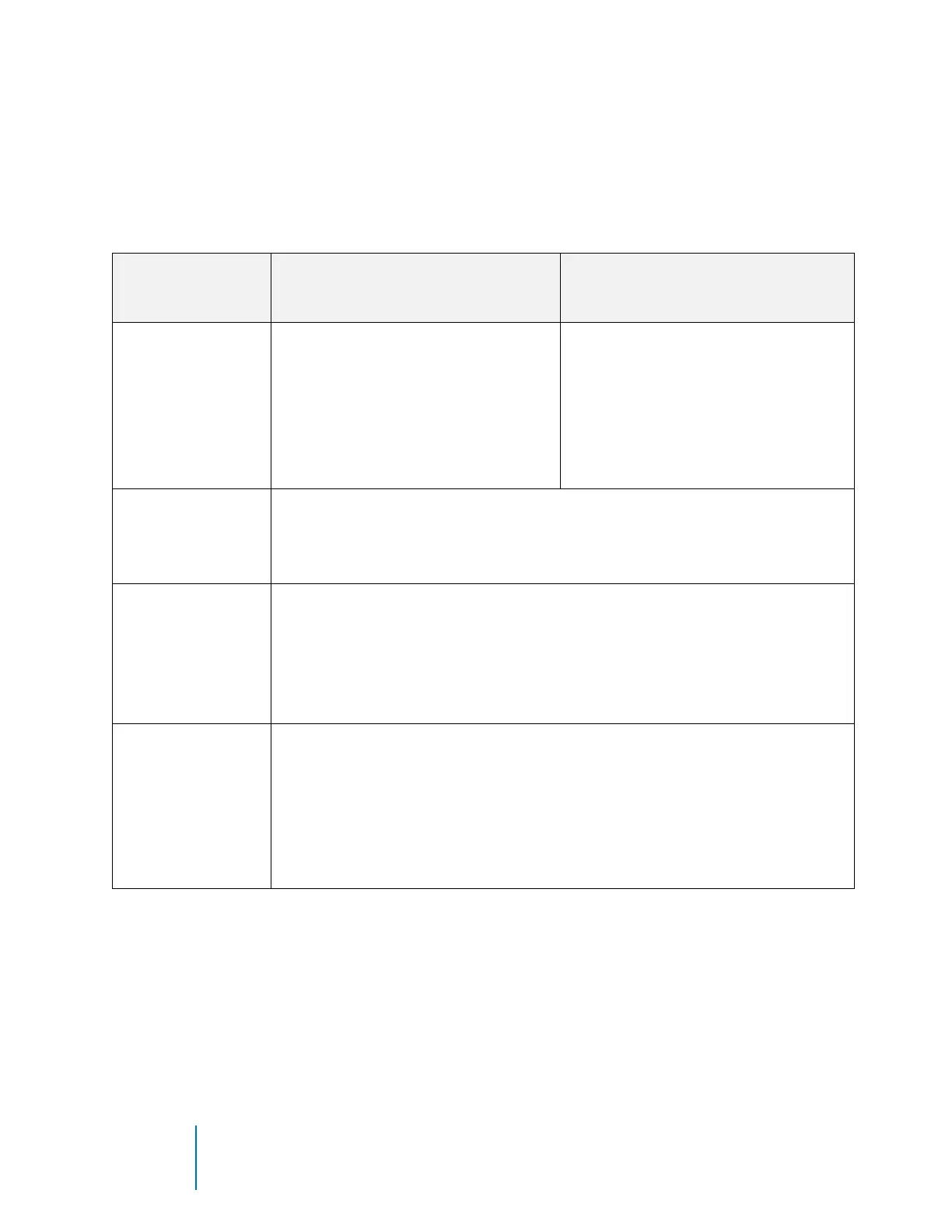
5.2.2. Oven Utility Connections
Utility connections vary slightly on different LCC/LCD models. Table 5 lists the
connection purposes and parameters. Refer to Figure 11 for a visual reference.
Table 5. Oven Utility Connections.
LCC/LCD Air Atmosphere models
with optional Water-cooled Model
LCC/LCD Nitrogen Atmosphere
models with standard water-
cooling
NITROGEN/CLEAN
DRY AIR INLET
• Clean Dry Air Inlet (70-80 psi
(4.83-5.52 bar))
• Used to purge water from coil
prior to heating oven
• 1/4” NPT female brass
connections provided
• Nitrogen Inlet (58-86 psi (4 -6
bar))
• Purge nitrogen, clean dry air
and water from coil prior to
heating the oven
• 1/4” NPT female brass
connections provided
• During cooling cycle, water flows through the water coil and out this
connection
• 3/8” NPT female brass connections provided
• Piping must be rated for up to 250°F (121°C)
• At the end of a cooling cycle, Nitrogen or Clean Dry Air is purged
through the water coil. Water and pressurized nitrogen/air exit this
connection for 30 seconds. Must be connected to gravity style drain
(no backpressure).
• 3/8” NPT female brass connections provided
• Piping must be rated for up to 250F (121C)
• Water Inlet for cooling
• 3/8” NPT female brass connections provided
• Requires 2 GPM flow at 16°C (55°F) to meet published cooling rates
• Maximum Pressure 100 PSI (6.89 Bar)
• Maintain a 20 PSI (1.4 bar) pressure differential at 2 GPM (7.6 lpm)
water flow