©2021 ITW EAE. All rights reserved. Despatch is a registered trademark in the U.S. and other
countries. No part of the contents of this manual may be reproduced, copied or transmitted in any form
or by any means without the written permission from ITW EAE - Despatch, unless for purchaser's
personal use.
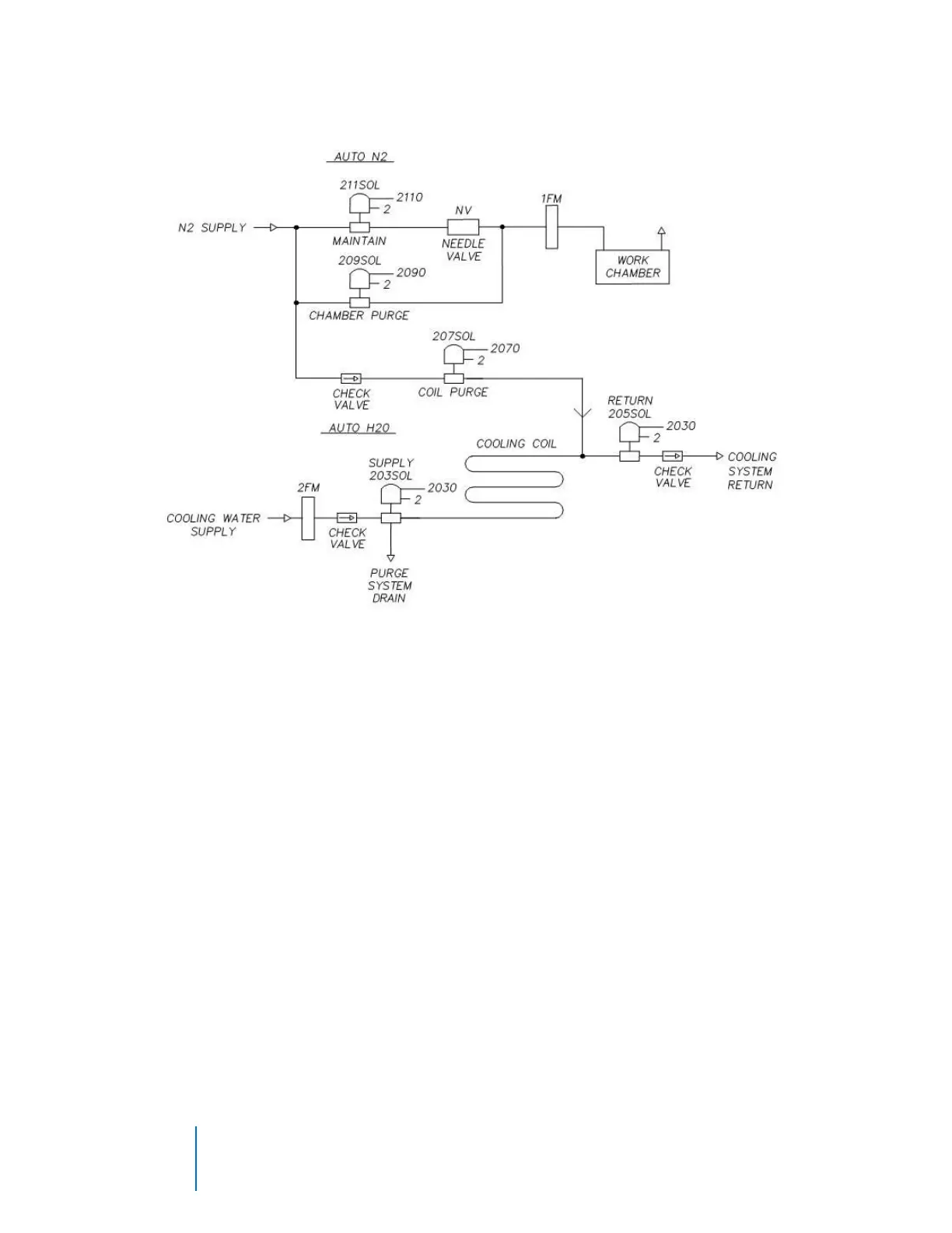
b. Water cooling flowmeter is located on the lower left side of the oven.
6.4.5. Manual Unlock and Main Disconnect
6.4.5.1. Manual Unlock
If a power failure occurs insert a torx tip tool (provided) and rotate 90 degrees
counterclockwise to allow the chamber door to open. The tool must be turned
back to the locked position to allow electrical operation again.
6.4.5.2. Main Disconnect Switch
This disconnect switch (yellow with red knob) is connected to the load break
switch behind the panel that disconnects or connects power from the main line.