Model TP-700
TP-700 Instruction Manual Rev. 4.1 Page 8 of 42
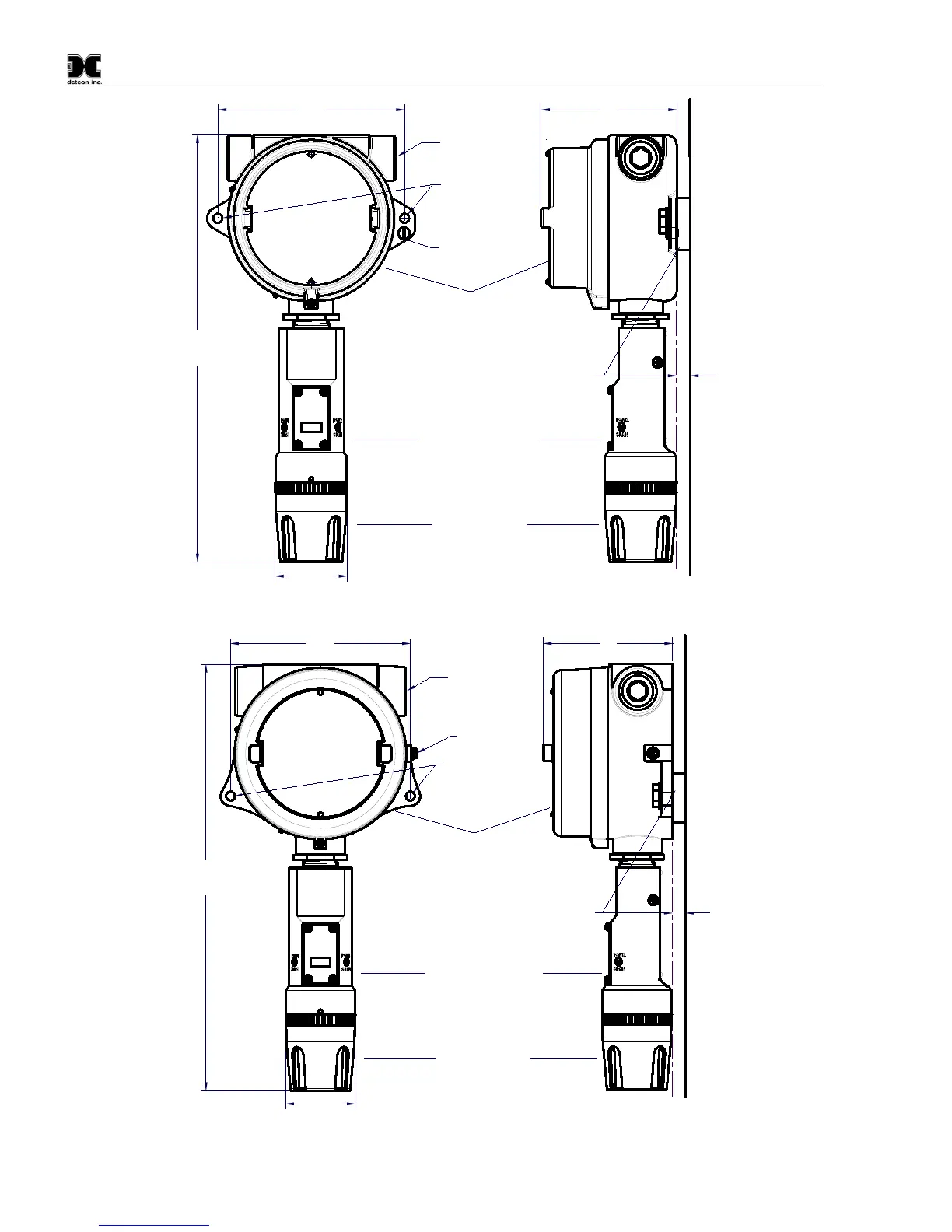
4"
3/4" NPT
Explosion Proof Enclosure
Junction-Box
Sensor Assembly
Splash Guard
(Detcon's SS Junction-Box shown)
2.125"
5.5"
12.5"
Typ.
Mounting
Bolt
Use Spacers to move the J-Box
and Sensor Assembly away
from the wall at least 0.25-0.5"
to allow access to Sensor.
Wall
(or other
mounting surface)
Ø0.265"
Spacer
Mounting Holes
8-32 Thread
Ground Point
MODEL
TP-700
detcon inc.
H
2
S Sensor
Figure 7 Outline and Mounting Dimensions (Stainless Steel Junction Box)
4"
3/4" NPT
Explosion Proof Enclosure
Junction-Box
Sensor Assembly
Splash Guard
(Detcon's Aluminum Junction-Box shown)
2.125"
5.5"
13.05"
Typ.
Mounting
Bolt
Use Spacers to move the J-Box
and Sensor Assembly away
from the wall at least 0.25-0.5"
to allow access to Sensor
Wall (or other
mounting surface)
Ø0.265" x2
Spacer
Mounting Holes
8-32 Thread
Ground Point
MODEL
TP-700
detcon inc.
H
2
S Sensor
Figure 8 Outline and Mounting Dimensions (Aluminum Junction Box)