Model TP-700
TP-700 Instruction Manual Rev. 4.1 Page 11 of 42
Table 2 Wire Gauge vs. Distance
AWG Wire Dia. Meters Feet
NOTE 1: Wiring table is based on stranded tinned copper wire and is designed to serve as a
reference only.
NOTE 2: Shielded cable is required for installations where cable trays or conduit runs include
high voltage lines or other possible sources of induced interference. Separate conduit runs are
highly recommended in these cases.
NOTE 3: The supply of power should be from an isolated source with over-current protection
as stipulated in table.
Terminal Connections
CAUTION: Do not apply System power to the sensor until all wiring is properly terminated. Refer to
Section 2.7 Initial Start Up
CAUTION: Do not apply power to the sensor assembly in a hazardous area unless the junction box
cover is tight and all electrical seals have been installed
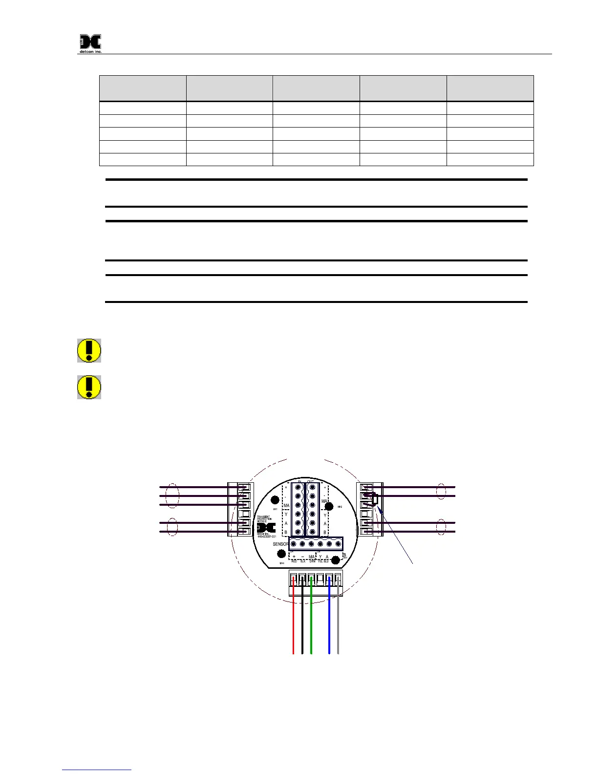
Customer
Supplied Wiring
(Out to next Device)
(+)
mA
(-)
A(+)
B(-)
Wiring to
Sensor Assembly
Wht
Blu
Red
Grn
Blk
Explosion
Proof
Junction Box
(+)
mA
(-)
A(+)
B(-)
(+)
mA
(-)
A(+)
B(-)
Customer
Supplied Wiring (In)
Modbus RS-485 to
Host Control Device
Power from and 4-20mA
out to Control Device
Install a 100-250 Ohm
resistor if the 4-20mA
output is not used
Modbus RS-485 to
next Device
Figure 11 Sensor Wire Connections