Model TP-700
TP-700 Instruction Manual Rev. 4.1 Page 2 of 42
declassifying the area. Electrical classifications are Class I, Division 1, Groups B, C, D, Class I, Zone 1, Group
IIB+H
2
and II 2G Ex d IIB+H
2
Gb.
Figure 1 ITM Circuit Functional Block Diagram
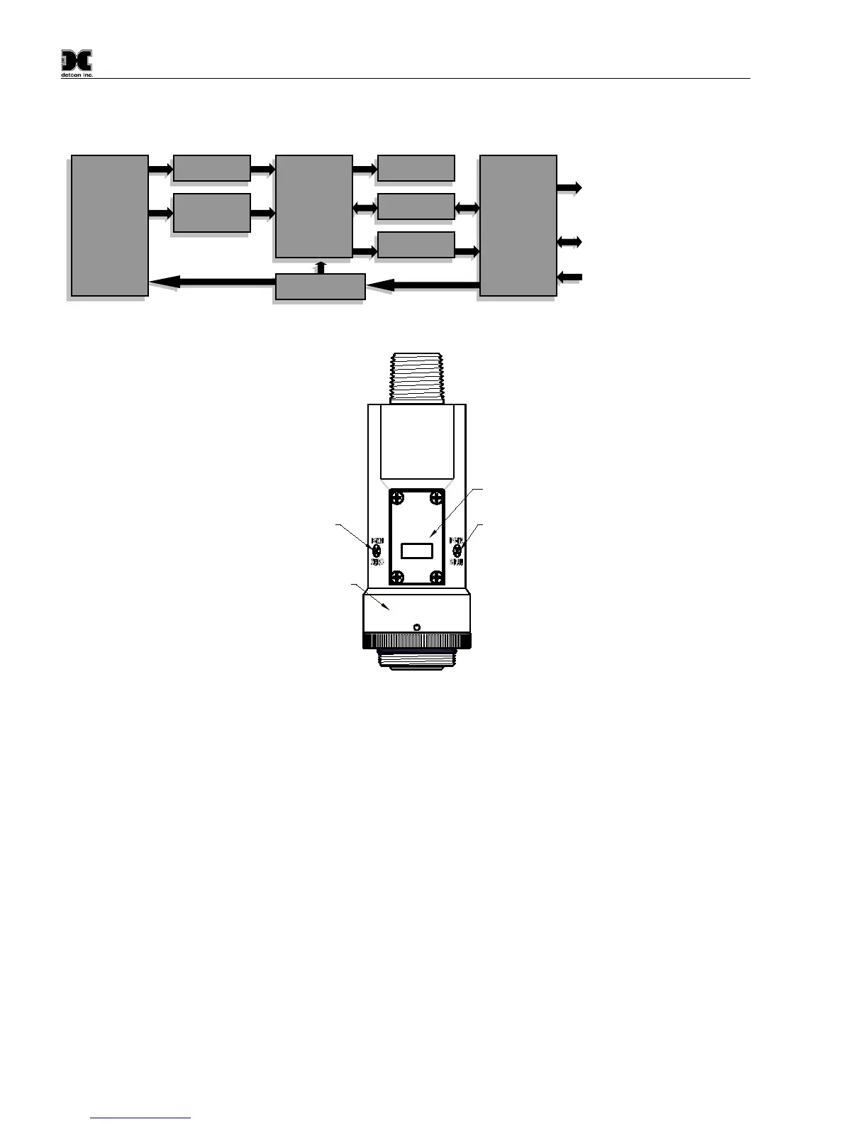
Program Switch #1
LED Display
Program Switch #2
Splash Guard Adapter
Locking Set-Screw
MODEL
TP-700
detcon inc.
H
2
S Sensor
Figure 2 Sensor Assembly Front View
1.3 Modular Mechanical Design
The Model TP-700 Sensor Assembly is completely modular and is made up of four parts (See Figure 3 for
Assembly Break-away):
1) TP-700 Intelligent Sensor Module (ITM)
2) Field Replaceable Plug-in H
2
S Gas Sensor
3) Model 700 Housing Bottom Assembly (contains the Housing Bottom, Flame Arrestor, Retaining Ring,
and rubber O-Ring’s)
4) Splash Guard.
NOTE: All metal components are constructed from electro polished 316 Stainless Steel in order to maximize
corrosion resistance in harsh environments.
I/O
Circuit
Protection
Micro-
Processor
Plug-In
Sensor
Element