Model TP-700
TP-700 Instruction Manual Rev. 4.1 Page 9 of 42
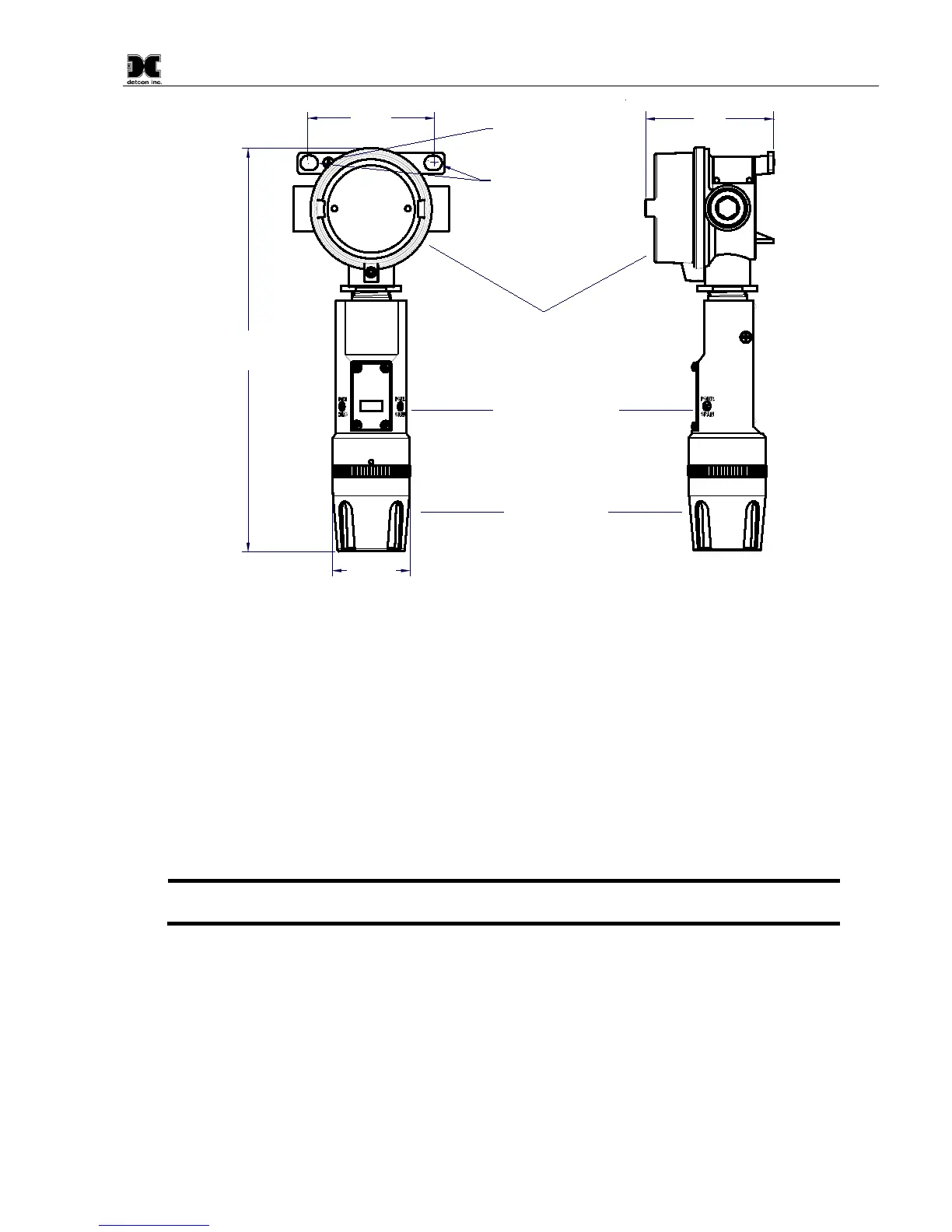
3.5"
Explosion Proof Enclosure
Junction-Box
Sensor Assembly
Splash Guard
(Detcon's Mini SS Junction-Box shown)
2.125"
3.45"
11"
Typ.
Mounting Holes
8-32 Thread
Ground Point
Ø0.4" x .475"
MODEL
TP-700
detcon inc.
H
2
S Sensor
Figure 9 Outline and Mounting Dimensions (Mini Stainless Steel Junction Box)
When mounting on a pole, secure the Junction Box to a suitable mounting plate and attach the mounting plate
to the pole using U-Bolts. (Pole-Mounting brackets for Detcon J-box accessories are available separately.)
2.5 Electrical Installation
The Sensor Assembly should be installed in accordance with local electrical codes. The sensor assemblies are
CSA/NRTL approved (US and Canada) for Class I, Division 1, Groups B, C, & D area classifications, and are
ATEX Approved for Class I, Zone 1, Group IIB+H
2
area classifications.
Proper electrical installation of the gas sensor is critical for conformance to Electrical Codes and to avoid damage
due to water leakage. Refer to Figure 10 and Figure 11 for proper electrical installation.
NOTE: If a conduit run exits the secondary port, repeat the installation technique shown in
Figure 10.
In Figure 10, the drain allows H
2
O condensation inside the conduit run to safely drain away from the sensor
assembly. The electrical seal fitting is required to meet the National Electrical Code per NEC Article 500-3d
(or Canadian Electrical Code Handbook Part 1 Section 18-154). Requirements for locations of electrical seals
are covered under NEC Article 501-5. Electrical seals also act as a secondary seal to prevent water from entering
the wiring terminal enclosure. However, they are not designed to provide an absolute watertight seal, especially
when used in the vertical orientation.