18
LT-2 027
EN
NOTE– After performing any service on the DV54 PAP, please test the unit to ensure
proper operation and calibrate, if necessary.
A. COVER REMOVAL
CAUTION– Failure to wear anti-static equipment during service may damage
this device.
1. If using a DV5HH, remove the heated humidifi er and unplug the tubing/humidi-
fi er air supply port plug from the back of the cover and re-plug it in the outlet
on the bottom cover.
2. Position the PAP on a clean, fl at surface with the keypad facing down.
3. Remove four T-20 screws from the bottom cover.
4. Lift the bottom cover straight up off the top cover.
NOTE– Attempting to reorient the PAP in order to lift the top cover, instead of the bot-
tom cover, may damage this device.
5. Wearing an anti-static device, carefully lift the chassis off the top cover.
B. COVER REPLACEMENT
CAUTION– Failure to wear anti-static equipment during service may damage
this device.
1. Wearing an anti-static device, search for and connect all loose wire harnesses.
2. Place the chassis into the top cover, with the keyboard facing the cover and fi t-
ting the control board around the screw posts in the cover.
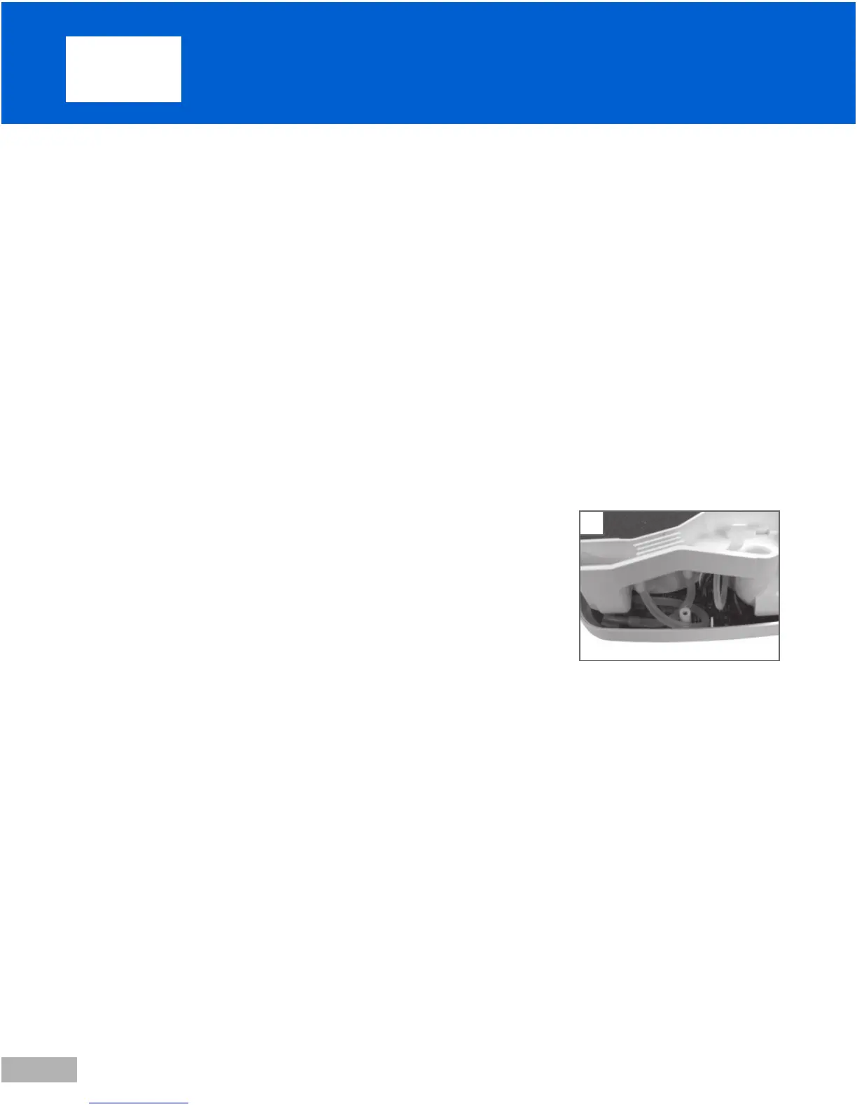
3. Connect all tubing, carefully creating the correct loops and eliminating any kink-
ing. (Fig. 1)
4. With the 1/8 inch inside bottom cover foam oriented correctly and lying fl at,
place the bottom cover over the chassis and onto the top cover, fi tting the
screw posts into proper alignment with the chassis and moving any protruding
wire harnesses and tubing away from the edges of the cover.
5. Replace four T-20 screws.
C. CONTROL PC BOARD REMOVAL
CAUTION– Failure to wear anti-static equipment during service may damage
this device.
1. Remove the cover. See instructions above.
2. Wearing an anti-static device, lift the cover off the chassis and place it, with the con-
trol board facing up and the blower facing down, onto a clean fl at surface.
3. Disconnect the three pieces of tubing from the outlet port side of the chassis.
4. Disconnect accessible wire harnesses: one behind and one to the left of the tub-
ing in step 3, one at the right corner under the keypad, and one on the outside
of the power supply board.
5. Remove one T-15 screw, located near the middle of the board beside LCD
screen. Lift the board off the chassis slowly and disconnect any remaining wire
harnesses from the control board.
6. Place control board keypad facing down onto a clean, fl at, static-free surface, if
returning to the unit.
9. S er vic e Instr uc t i ons
1