32
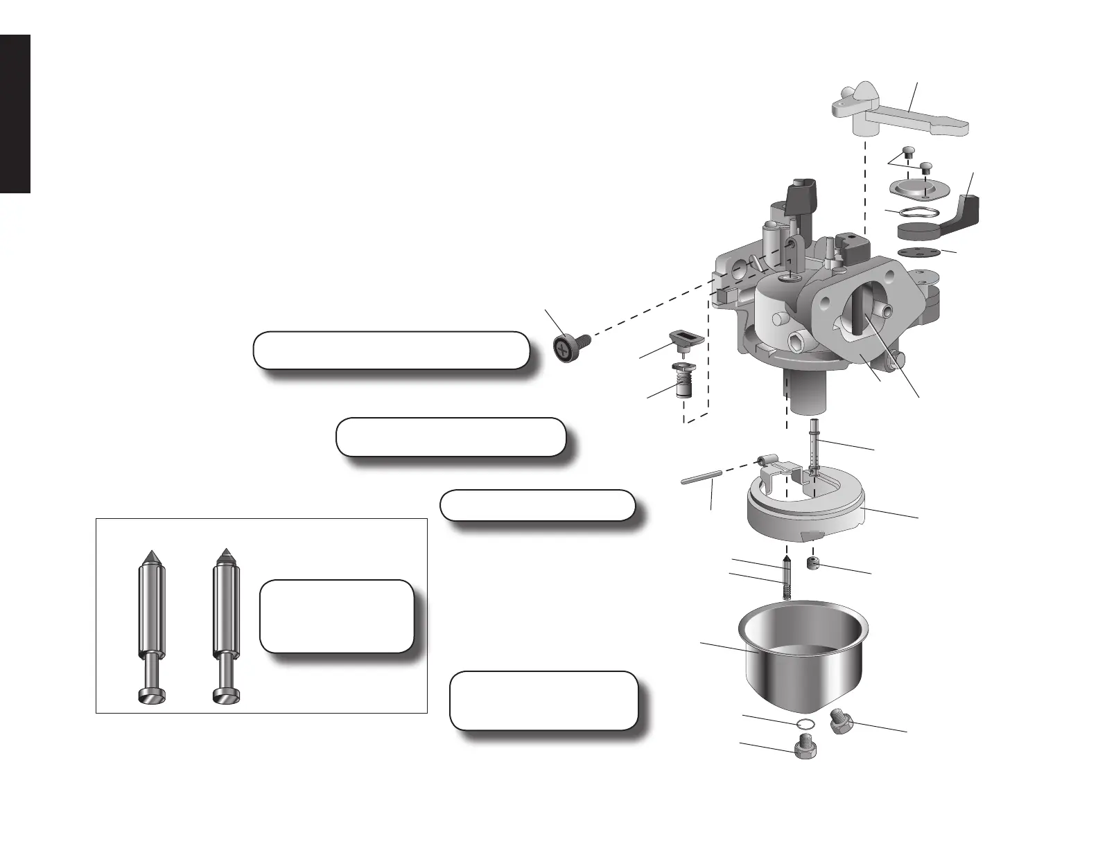
MODELS DW168F-2H, DW168F-2E,
DW177F-H, DW177F-E, DW188F-H
ASSEMBLY
D2. O-Ring
E2.Fuelvalvegasket
G2. Lever spring
H2. Fuel valve lever
I2.Chokelever
I4. Main jet
J2. Carburetor bowl
K2. Fuel drain bolt
L2. Set bolt
M2. Float pin
N2. Float valve spring
O2 Float valve
P2. Float
Q2. Throttle stop screw
R2. Pilot Jet
S2. Throttle stop screw seat
T2.Chokevalve
U2. Carburetor Body
V2.Screw(2)
W2. Lever setting plate
X2. E-tube
Adjustthrottlestopscrew(Q2).SeeSpeed/
Governor Adjustment under Maintenance.
Cleancarburetorbody(U2).
Check for smooth movement after
installingthefloat.(P2).
After assembling set bolt
(L2) and carburetor check for
anysignsoffuelleaking.
I2
J2
S2
R2
V2
W2
G2
H2
E2
Q2
P2
O2
M2
L2
K2
U2
Before reassembling
float (P2), check float
valve for wear and replace
if needed.
OK REPLACE
T2
N2
D2
X2
I4